


Draw summing amplifier circuit using operational amplifier.
Answer
597.3k+ views
Hint
An operational amplifier can also perform summing operations. We can even design an operation amplifier circuit to combine using a number of input signals and to produce a single output as a weighted sum of input signals. And we also know that The summing Amplifier is one variation of inverting amplifiers.
Complete step-by-step solution:
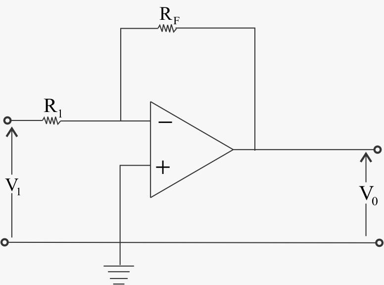
Summing amplifier is basically an operational amplifier circuit that can combine numbers of input signals to a single output that is the weighted sum of the applied inputs. hile inverting amplifier there is only one voltage signal applied to the inverting input as shown below,
Summing amplifier can simply be made via Inverting amplifier, For this we connect several input terminals in parallel to the existing input terminals, like given below:
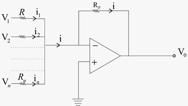
Here, n numbers of input terminals are connected in parallel. Here, in the circuit, the non-inverting terminal of the op amp is grounded, hence potential at that terminal is zero. As the operational amplifier is considered as an ideal operational amplifier, the potential of the inverting terminal is also zero.
Therefore, at node 1 elastic potential is also zero. From the circuit, it is also clear that the current i is the sum of currents of input terminals.
Therefore,
\[i = {i_{}} + {i_2} + {i_3} + ......... + {i_n}\]
\[i = \dfrac{{{v_1} - 0}}{{{R_1}}} + \dfrac{{{v_2} - 0}}{{{R_2}}} + ......... + \dfrac{{{v_n} - 0}}{{{R_n}}}\]
Now, in the case of an ideal op amp the current at the inverting and non-inverting terminal are zero. Now, according to Kirchhoff Current Law, the whole input current passes through the feedback path of resistance Rf. That means,
\[i = \dfrac{{0 - {v_0}}}{{{R_f}}} = - \dfrac{{{v_0}}}{{{R_f}}}\]
From, equation (i) and (ii), we get,
\[\dfrac{{{v_1}}}{{{R_1}}} + \dfrac{{{v_2}}}{{{R_2}}} + ......... + \dfrac{{{v_n}}}{{{R_n}}} = - \dfrac{{{v_0}}}{{{R_f}}}\]
\[{v_0} = - ({R_f}\dfrac{{{v_1}}}{{{R_1}}} + {R_f}\dfrac{{{v_2}}}{{{R_2}}} + ......... + {R_f}\dfrac{{{v_n}}}{{{R_n}}})\]
This indicates that output voltage v0 is a weighted sum of numbers of input voltages.
Note:-
Talking about summing amplifiers is a type of operational amplifier circuit which can be used to sum signals. And the sum of the input signal is amplified by a certain factor and made available at the output. Any number of input signals can be summed using an operational amplifier.
An operational amplifier can also perform summing operations. We can even design an operation amplifier circuit to combine using a number of input signals and to produce a single output as a weighted sum of input signals. And we also know that The summing Amplifier is one variation of inverting amplifiers.
Complete step-by-step solution:
Summing amplifier is basically an operational amplifier circuit that can combine numbers of input signals to a single output that is the weighted sum of the applied inputs. hile inverting amplifier there is only one voltage signal applied to the inverting input as shown below,
Summing amplifier can simply be made via Inverting amplifier, For this we connect several input terminals in parallel to the existing input terminals, like given below:
Here, n numbers of input terminals are connected in parallel. Here, in the circuit, the non-inverting terminal of the op amp is grounded, hence potential at that terminal is zero. As the operational amplifier is considered as an ideal operational amplifier, the potential of the inverting terminal is also zero.
Therefore, at node 1 elastic potential is also zero. From the circuit, it is also clear that the current i is the sum of currents of input terminals.
Therefore,
\[i = {i_{}} + {i_2} + {i_3} + ......... + {i_n}\]
\[i = \dfrac{{{v_1} - 0}}{{{R_1}}} + \dfrac{{{v_2} - 0}}{{{R_2}}} + ......... + \dfrac{{{v_n} - 0}}{{{R_n}}}\]
Now, in the case of an ideal op amp the current at the inverting and non-inverting terminal are zero. Now, according to Kirchhoff Current Law, the whole input current passes through the feedback path of resistance Rf. That means,
\[i = \dfrac{{0 - {v_0}}}{{{R_f}}} = - \dfrac{{{v_0}}}{{{R_f}}}\]
From, equation (i) and (ii), we get,
\[\dfrac{{{v_1}}}{{{R_1}}} + \dfrac{{{v_2}}}{{{R_2}}} + ......... + \dfrac{{{v_n}}}{{{R_n}}} = - \dfrac{{{v_0}}}{{{R_f}}}\]
\[{v_0} = - ({R_f}\dfrac{{{v_1}}}{{{R_1}}} + {R_f}\dfrac{{{v_2}}}{{{R_2}}} + ......... + {R_f}\dfrac{{{v_n}}}{{{R_n}}})\]
This indicates that output voltage v0 is a weighted sum of numbers of input voltages.
Note:-
Talking about summing amplifiers is a type of operational amplifier circuit which can be used to sum signals. And the sum of the input signal is amplified by a certain factor and made available at the output. Any number of input signals can be summed using an operational amplifier.
Recently Updated Pages
How is Abiogenesis Theory Disproved Experimentally?
In a plane electromagnetic wave the electric field class 12 physics CBSE
A plane electromagnetic wave travels in vacuum along class 12 physics CBSE
The branch of science which deals with nature and natural class 10 physics CBSE
Understanding the Sun's Density: Exploring the Mass Density of a Hot Plasma - FAQs and Data Analysis
Where is the Centre for Environmental Education Located?
Trending doubts
Which are the Top 10 Largest Countries of the World?
Draw a labelled sketch of the human eye class 12 physics CBSE
Which state in the country is at the forefront in controlling class 12 social science CBSE
Mention the role of cyanobacteria as a biofertiliz class 12 biology ICSE
Where is the largest hydroelectric power station located class 12 biology CBSE
Which country did Danny Casey play for class 12 english CBSE