


Draw circuit arrangement for studying input and output characteristics of n-p-n-transistor in CE configuration and explain its action with the help of graphs.
Answer
618.9k+ views
Hint: Transistors are of two types i.e. n-p-n and p-n-p. A n-p-n transistor can be biased in three ways, which are Common emitter (CE), Common base (CB) and Common collector (CC). For a n-p-n transistor in CE configuration, the input terminal of the transistor is the base and output terminal is the collector. Input characteristic curve describes the variation in the input current based on the input voltage. Output characteristic curve describes the variation in the output current based on the output voltage keeping the input current constant.
Complete step by step answer:
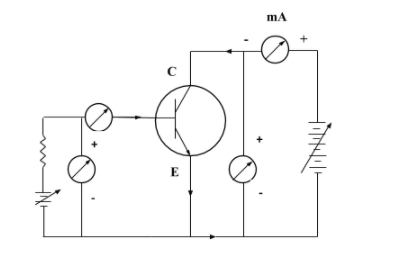
Above is the circuit arrangement of the n-p-n transistor in CE configuration to study its input and output characteristics.
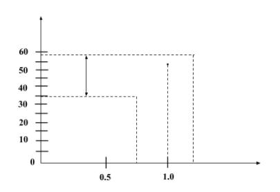
Input Characteristics: The curve drawn between the base current (${I}_{B}$) and base-emitter voltage (${V}_{BE}$) gives the input characteristics of n-p-n transistors in CE configuration. It helps to find the input dynamic resistance of the transistor. It is denoted by the slope of the input characteristic curve. For the input characteristic curve, the reading of base currents are taken with the help of ammeter on emitter-base voltage (${V}_{BE}$) at constant collector-emitter current (${I}_{CE}$). Input characteristic curve is given below:
Output Characteristics: The curve drawn between the collector current (${I}_{C}$) and collector-emitter voltage (${V}_{CE}$) at constant base current (${I}_{B}$) gives the output characteristics of n-p-n transistor in CE configuration. The value of the slope in the output characteristic graph gives the output dynamic resistance. The output characteristic curve for a n-p-n transistor in CE configuration is given below:
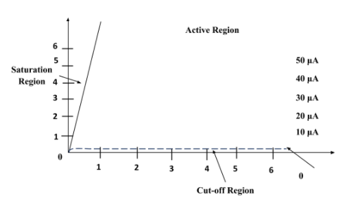
In the active region of output characteristic curve, the collector current (${I}_{C}$) slightly increases with increase in collector-emitter current (${I}_{CE}$) at constant voltage. When the collector-emitter current falls, the collector current also falls rapidly. In the saturation region, the collector current (${I}_{C}$) is independent of the input current (${I}_{B}$). In the active region, base current is very small but not zero. It is equal to the reverse leakage current.
Note:
Input resistance of the CE configuration is comparatively higher than that for the CB configuration. The output resistance of the CE configuration is lesser than that for the CB configuration. The slope of the curve of output characteristic curve in CE configuration is comparatively greater than the output characteristic curve for the CB configuration. The n-p-n and p-n-p transistors are used as amplifiers to amplify the signals. As the mobility of electrons is greater as compared to that of holes, n-p-n transistors are preferred over p-n-p transistors.
Complete step by step answer:
Above is the circuit arrangement of the n-p-n transistor in CE configuration to study its input and output characteristics.
Input Characteristics: The curve drawn between the base current (${I}_{B}$) and base-emitter voltage (${V}_{BE}$) gives the input characteristics of n-p-n transistors in CE configuration. It helps to find the input dynamic resistance of the transistor. It is denoted by the slope of the input characteristic curve. For the input characteristic curve, the reading of base currents are taken with the help of ammeter on emitter-base voltage (${V}_{BE}$) at constant collector-emitter current (${I}_{CE}$). Input characteristic curve is given below:
Output Characteristics: The curve drawn between the collector current (${I}_{C}$) and collector-emitter voltage (${V}_{CE}$) at constant base current (${I}_{B}$) gives the output characteristics of n-p-n transistor in CE configuration. The value of the slope in the output characteristic graph gives the output dynamic resistance. The output characteristic curve for a n-p-n transistor in CE configuration is given below:
In the active region of output characteristic curve, the collector current (${I}_{C}$) slightly increases with increase in collector-emitter current (${I}_{CE}$) at constant voltage. When the collector-emitter current falls, the collector current also falls rapidly. In the saturation region, the collector current (${I}_{C}$) is independent of the input current (${I}_{B}$). In the active region, base current is very small but not zero. It is equal to the reverse leakage current.
Note:
Input resistance of the CE configuration is comparatively higher than that for the CB configuration. The output resistance of the CE configuration is lesser than that for the CB configuration. The slope of the curve of output characteristic curve in CE configuration is comparatively greater than the output characteristic curve for the CB configuration. The n-p-n and p-n-p transistors are used as amplifiers to amplify the signals. As the mobility of electrons is greater as compared to that of holes, n-p-n transistors are preferred over p-n-p transistors.
Recently Updated Pages
Master Class 12 Business Studies: Engaging Questions & Answers for Success
Master Class 12 Biology: Engaging Questions & Answers for Success
Master Class 12 Chemistry: Engaging Questions & Answers for Success
Class 12 Question and Answer - Your Ultimate Solutions Guide
Master Class 11 English: Engaging Questions & Answers for Success
Master Class 11 Social Science: Engaging Questions & Answers for Success
Trending doubts
Which are the Top 10 Largest Countries of the World?
Draw a labelled sketch of the human eye class 12 physics CBSE
Differentiate between homogeneous and heterogeneous class 12 chemistry CBSE
Why is the cell called the structural and functional class 12 biology CBSE
Draw ray diagrams each showing i myopic eye and ii class 12 physics CBSE
Which is the correct genotypic ratio of mendel dihybrid class 12 biology CBSE