


Draw a labelled diagram of a step-up transformer. Obtain the ratio of secondary to primary voltage in terms of the number of turns and the current in the two coils.
Answer
620.7k+ views
Hint:In this question, first draw the transformer circuit then apply the Kirchhoff’s voltage Law that is in a closed-circuit loop, the summation of the voltage across the loop will be zero and also apply the Faraday’s Law to derive the EMF equation.
Complete step by step solution:
First of all, we will draw the circuit diagram of the transformer as,
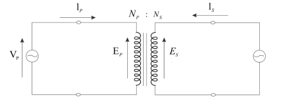
Where, subscripts $P$ and $S$ denote the primary (input) and secondary (output) windings and $E$ denotes the induced voltage across the winding.
Let’s assume that the connecting wires are ideal, that is the voltage drop across the connecting wire is zero.
As we know that according to Kirchhoff’s Voltage law, in a closed-circuit loop, the summation of the voltage across the loop will be zero.
Now, applying Kirchhoff’s Voltage law in both primary and secondary loops as,
\[
{V_P} = {E_P} \\
{V_S} = {E_S} \\
\]
According to Faraday’s law, the Emf induced in the circuit is directly proportional to the rate of change of the flux. Now, apply the Faraday’s law for the primary circuit,
\[{E_P} = - {N_P}\dfrac{{d\phi }}{{dt}}\]
Here, the Emf induced in the primary circuit is ${E_p}$, the number of turns in the primary coil is ${N_p}$, and the rate of change of flux is $\dfrac{{d\phi }}{{dt}}$.
As we obtain from the Kirchhoff’s law that is ${V_p} = {E_p}$, so above equation become,
\[
{E_P} = - {N_P}\dfrac{{d\phi }}{{dt}} \\
{V_P} = - {N_P}\dfrac{{d\phi }}{{dt}} \\
\] …… (1)
Similarly, apply the Faraday’s law for the secondary circuit,
\[{E_S} = - {N_S}\dfrac{{d\phi }}{{dt}}\]
Here, the Emf induced in the secondary circuit is ${E_S}$, the number of turns in the secondary coil is ${N_S}$, and the rate of change of flux is $\dfrac{{d\phi }}{{dt}}$.
As we obtain from the Kirchhoff’s law that is ${V_S} = {E_S}$, so above equation become,
\[
{E_S} = - {N_S}\dfrac{{d\phi }}{{dt}} \\
{V_S} = - {N_S}\dfrac{{d\phi }}{{dt}} \\
\] …… (2)
Now, divide equation (1) by equation (2), to obtain
\[
\dfrac{{{V_ P}}}{{{V_S}}} = \dfrac{{ - {N_ P}\dfrac{{d\phi }}{{dt}}}}{{ - {N_S}\dfrac{{d\phi }}{{dt}}}} \\
\dfrac{{{V_P}}}{{{V_S}}} = \dfrac{{{N_P}}}{{{N_S}}} \\
\Rightarrow \dfrac{{{V_P}}}{{{N_P}}} = \dfrac{{{V_S}}}{{{N_S}}} \\
\Rightarrow \dfrac{{{V_S}}}{{{V_P}}} = \dfrac{{{N_S}}}{{{N_P}}} \\
\] …… (3)
Now, derive the equation in terms of primary and the secondary current. We know that the power input to the coil is equal to the power output as,
$
{\text{Power}}\;{\text{input}} = {\text{Power}}\;{\text{output}} \\
{I_p}{V_p} = {I_s}{V_s} \\
\Rightarrow \dfrac{{{V_s}}}{{{V_p}}} = \dfrac{{{I_p}}}{{{I_s}}} \\
$ ….. (4)
Now, we compare equation (3) and (4) as,
$ \Rightarrow \dfrac{{{V_s}}}{{{V_p}}} = \dfrac{{{I_p}}}{{{I_s}}} = \dfrac{{{N_s}}}{{{N_p}}}$
For, step-up transformer the output voltage must be greater than the input voltage.
So, the condition for step-up transformer are
\[
\Rightarrow \dfrac{{{V_{out}}}}{{{V_{in}}}} > 1 \\
\Rightarrow \dfrac{{{N_S}}}{{{N_P}}} > 1 \\
\Rightarrow {N_S} > {N_P} \\
\]
Thus, the number of turns in the secondary coil should be greater than the number of turns in the primary coil.
Note:The above expression is valid for ideal conditions only. If the resistivity and dimensions of the wire are given, then we will have to consider the resistance of the wire. In practice, the losses during the electricity transmission are lesser for higher voltages. Thus, the step-up transformers are used before the transmission lines. And step-down transformers are used at the end of the transmission lines or receiving end, since the household appliances work on relatively lower voltages.
Complete step by step solution:
First of all, we will draw the circuit diagram of the transformer as,
Where, subscripts $P$ and $S$ denote the primary (input) and secondary (output) windings and $E$ denotes the induced voltage across the winding.
Let’s assume that the connecting wires are ideal, that is the voltage drop across the connecting wire is zero.
As we know that according to Kirchhoff’s Voltage law, in a closed-circuit loop, the summation of the voltage across the loop will be zero.
Now, applying Kirchhoff’s Voltage law in both primary and secondary loops as,
\[
{V_P} = {E_P} \\
{V_S} = {E_S} \\
\]
According to Faraday’s law, the Emf induced in the circuit is directly proportional to the rate of change of the flux. Now, apply the Faraday’s law for the primary circuit,
\[{E_P} = - {N_P}\dfrac{{d\phi }}{{dt}}\]
Here, the Emf induced in the primary circuit is ${E_p}$, the number of turns in the primary coil is ${N_p}$, and the rate of change of flux is $\dfrac{{d\phi }}{{dt}}$.
As we obtain from the Kirchhoff’s law that is ${V_p} = {E_p}$, so above equation become,
\[
{E_P} = - {N_P}\dfrac{{d\phi }}{{dt}} \\
{V_P} = - {N_P}\dfrac{{d\phi }}{{dt}} \\
\] …… (1)
Similarly, apply the Faraday’s law for the secondary circuit,
\[{E_S} = - {N_S}\dfrac{{d\phi }}{{dt}}\]
Here, the Emf induced in the secondary circuit is ${E_S}$, the number of turns in the secondary coil is ${N_S}$, and the rate of change of flux is $\dfrac{{d\phi }}{{dt}}$.
As we obtain from the Kirchhoff’s law that is ${V_S} = {E_S}$, so above equation become,
\[
{E_S} = - {N_S}\dfrac{{d\phi }}{{dt}} \\
{V_S} = - {N_S}\dfrac{{d\phi }}{{dt}} \\
\] …… (2)
Now, divide equation (1) by equation (2), to obtain
\[
\dfrac{{{V_ P}}}{{{V_S}}} = \dfrac{{ - {N_ P}\dfrac{{d\phi }}{{dt}}}}{{ - {N_S}\dfrac{{d\phi }}{{dt}}}} \\
\dfrac{{{V_P}}}{{{V_S}}} = \dfrac{{{N_P}}}{{{N_S}}} \\
\Rightarrow \dfrac{{{V_P}}}{{{N_P}}} = \dfrac{{{V_S}}}{{{N_S}}} \\
\Rightarrow \dfrac{{{V_S}}}{{{V_P}}} = \dfrac{{{N_S}}}{{{N_P}}} \\
\] …… (3)
Now, derive the equation in terms of primary and the secondary current. We know that the power input to the coil is equal to the power output as,
$
{\text{Power}}\;{\text{input}} = {\text{Power}}\;{\text{output}} \\
{I_p}{V_p} = {I_s}{V_s} \\
\Rightarrow \dfrac{{{V_s}}}{{{V_p}}} = \dfrac{{{I_p}}}{{{I_s}}} \\
$ ….. (4)
Now, we compare equation (3) and (4) as,
$ \Rightarrow \dfrac{{{V_s}}}{{{V_p}}} = \dfrac{{{I_p}}}{{{I_s}}} = \dfrac{{{N_s}}}{{{N_p}}}$
For, step-up transformer the output voltage must be greater than the input voltage.
So, the condition for step-up transformer are
\[
\Rightarrow \dfrac{{{V_{out}}}}{{{V_{in}}}} > 1 \\
\Rightarrow \dfrac{{{N_S}}}{{{N_P}}} > 1 \\
\Rightarrow {N_S} > {N_P} \\
\]
Thus, the number of turns in the secondary coil should be greater than the number of turns in the primary coil.
Note:The above expression is valid for ideal conditions only. If the resistivity and dimensions of the wire are given, then we will have to consider the resistance of the wire. In practice, the losses during the electricity transmission are lesser for higher voltages. Thus, the step-up transformers are used before the transmission lines. And step-down transformers are used at the end of the transmission lines or receiving end, since the household appliances work on relatively lower voltages.
Recently Updated Pages
Master Class 12 Business Studies: Engaging Questions & Answers for Success
Master Class 12 Biology: Engaging Questions & Answers for Success
Master Class 12 Chemistry: Engaging Questions & Answers for Success
Class 12 Question and Answer - Your Ultimate Solutions Guide
Master Class 11 English: Engaging Questions & Answers for Success
Master Class 11 Social Science: Engaging Questions & Answers for Success
Trending doubts
Which are the Top 10 Largest Countries of the World?
Draw a labelled sketch of the human eye class 12 physics CBSE
Differentiate between homogeneous and heterogeneous class 12 chemistry CBSE
Why is the cell called the structural and functional class 12 biology CBSE
Draw ray diagrams each showing i myopic eye and ii class 12 physics CBSE
Which is the correct genotypic ratio of mendel dihybrid class 12 biology CBSE