


Draw a circuit diagram of a full wave rectifier. Explain its working and draw the input and output waveforms.
Answer
562.9k+ views
- Hint: First let us draw the circuit diagram of the full wave rectifier made of junction diode so that we may know about its components and what role they play. Further will understand the insights of the rectifier and in what way modifications can be to the rectifier. Then finally will draw the waveforms indicating how the input and the output signal varies in a given time interval.
Complete step-by-step solution
So let us begin by drawing the circuit diagram.
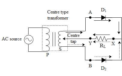
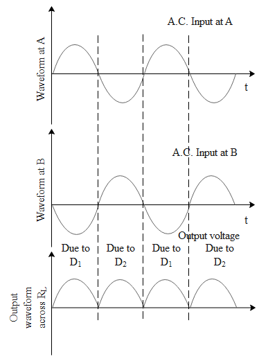
A simple full way rectifier consists of two transformers mutually inducted and two diodes which filter the negative cycle of alternating current. At any instant the voltage at A(input voltage of diode 1) and end B (input voltage of diode 2) of the secondary with respect to the centre tap will be out of phase. Suppose during a positive half cycle of Ac input, the end A is positive and end B is negative with respect to the centre tap. Then diode 1 gets forward biased(allows the flow of current) and diode 2 gets reversed biased(does not allow the flow of current). Hence the current flows through the diode 1 towards the centre tap along the path AXY as shown in the above diagram. Similarly, during the negative half cycle of Ac input the end B becomes positive and end A becomes negative. Hence diode 1 gets reversed biased and diode 2 gets forward biased resulting in the current to flow from diode 2 to the centre tap along the path BXY as shown in the above diagram. As during both the half cycles the input a.c. the current through the load resistor will flow from X to Y and will keep on pulsating. Given below is the waveform for the full wave rectifier indicating inputs of AC and the output voltage.
Note: This type of rectifiers are used to generate D.C current by introducing a filter circuit to the rectifier. A half wave rectifier also rectifies the wave but it does once for every single cycle of the input. These full wave rectifiers can be used to generate different signals by introducing slight modifications. It is also to be noted that when a diode is connected in a forward biased position across a given potential difference. The current in the circuit will not be proportional to the applied voltage if its value is very small. The minimum voltage required across a diode such that the current across it is proportional to the potential difference is called threshold voltage or the cut-in voltage.
Complete step-by-step solution
So let us begin by drawing the circuit diagram.
A simple full way rectifier consists of two transformers mutually inducted and two diodes which filter the negative cycle of alternating current. At any instant the voltage at A(input voltage of diode 1) and end B (input voltage of diode 2) of the secondary with respect to the centre tap will be out of phase. Suppose during a positive half cycle of Ac input, the end A is positive and end B is negative with respect to the centre tap. Then diode 1 gets forward biased(allows the flow of current) and diode 2 gets reversed biased(does not allow the flow of current). Hence the current flows through the diode 1 towards the centre tap along the path AXY as shown in the above diagram. Similarly, during the negative half cycle of Ac input the end B becomes positive and end A becomes negative. Hence diode 1 gets reversed biased and diode 2 gets forward biased resulting in the current to flow from diode 2 to the centre tap along the path BXY as shown in the above diagram. As during both the half cycles the input a.c. the current through the load resistor will flow from X to Y and will keep on pulsating. Given below is the waveform for the full wave rectifier indicating inputs of AC and the output voltage.
Note: This type of rectifiers are used to generate D.C current by introducing a filter circuit to the rectifier. A half wave rectifier also rectifies the wave but it does once for every single cycle of the input. These full wave rectifiers can be used to generate different signals by introducing slight modifications. It is also to be noted that when a diode is connected in a forward biased position across a given potential difference. The current in the circuit will not be proportional to the applied voltage if its value is very small. The minimum voltage required across a diode such that the current across it is proportional to the potential difference is called threshold voltage or the cut-in voltage.
Recently Updated Pages
Master Class 12 Economics: Engaging Questions & Answers for Success
Master Class 12 English: Engaging Questions & Answers for Success
Master Class 12 Social Science: Engaging Questions & Answers for Success
Master Class 12 Maths: Engaging Questions & Answers for Success
Master Class 12 Physics: Engaging Questions & Answers for Success
Master Class 12 Business Studies: Engaging Questions & Answers for Success
Trending doubts
Which are the Top 10 Largest Countries of the World?
Draw a labelled sketch of the human eye class 12 physics CBSE
Differentiate between homogeneous and heterogeneous class 12 chemistry CBSE
Why is the cell called the structural and functional class 12 biology CBSE
Draw ray diagrams each showing i myopic eye and ii class 12 physics CBSE
Which is the correct genotypic ratio of mendel dihybrid class 12 biology CBSE