


How does this allow us to measure the potential difference across a diode?
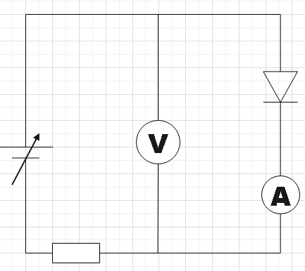
An experiment involves measuring the potential difference across a diode when it just begins to conduct. Which of the following circuits would allow this measurement to be made?
A.
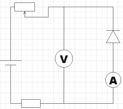
B.
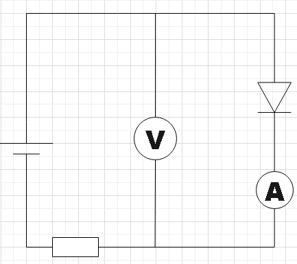
C.
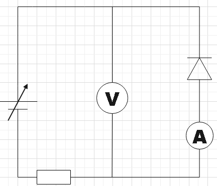
D.
Answer
533.4k+ views
Hint: As a very first step, you could have a close look at the given circuits and then understand the connections properly and then also recall the working of a pn junction diode. You also have ammeters in every circuit. So, you would be also able to measure the current in the circuit by using this ammeter.
Complete answer:
In the question, we are given four circuits set up for the purpose measuring the potential difference across the diodes in them. We are supposed to find which of the given circuits will correctly find the potential difference.
In circuit A we see that the diode is forward biased, that is, the positive of the voltage source is connected to the p-side of the diode and n-side to its negative terminal. If we increase the voltage of the source slowly by setting it initially to zero, the ammeter will show a small current and simultaneously you could also measure the potential difference across the diode in the voltmeter. You could follow the same steps for circuit D. But the voltmeter will be measuring the reverse bias voltage there.
Therefore, we found circuits A and D to be able to measure the potential difference across the diode.
Note:
One should be careful while doing the experiment. For circuit D, if you keep increasing the voltage of the source, chances are there for the diode getting damaged. Due to the fact that the marginal impedance of the diode that is in conduction mode remains less than the source impedance of supply voltage, the voltage measured would remain$\sim 0.6V$.
Recently Updated Pages
Master Class 12 Economics: Engaging Questions & Answers for Success
Master Class 12 Physics: Engaging Questions & Answers for Success
Master Class 12 English: Engaging Questions & Answers for Success
Master Class 12 Social Science: Engaging Questions & Answers for Success
Master Class 12 Maths: Engaging Questions & Answers for Success
Master Class 12 Business Studies: Engaging Questions & Answers for Success
Trending doubts
Which are the Top 10 Largest Countries of the World?
What are the major means of transport Explain each class 12 social science CBSE
Draw a labelled sketch of the human eye class 12 physics CBSE
Why cannot DNA pass through cell membranes class 12 biology CBSE
Differentiate between insitu conservation and exsitu class 12 biology CBSE
Draw a neat and well labeled diagram of TS of ovary class 12 biology CBSE