


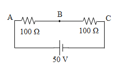
Consider the diagram shown.
A voltmeter of resistance $150\Omega $ is connected across A and B. the potential drop across B and C measured by voltmeter is
a)29V
b)27V
c)31V
d)30V
Answer
627.3k+ views
Hint: In the above question it is given to us that the voltmeter of resistance $150\Omega $is connected in parallel with the resistance 100 ohms towards A. First we will determine the equivalent resistance in the circuit. Further using ohm's law we will determine the current in the circuit. Again using ohm's law we will determine the voltage across the BC.
Formula used:
$V=IR$
${{R}_{P}}=\dfrac{rR}{R+r}$
Complete step by step answer:
Initially it is given to us that the voltmeter of resistance $150\Omega $is connected across AB. If there are two resistors i.e. r and R connected in parallel, the equivalent resistance ${{R}_{P}}$ in parallel is given by,
${{R}_{P}}=\dfrac{rR}{R+r}$
Hence using this equation the net resistance across AB is equal to,
$\begin{align}
& {{R}_{P}}=\dfrac{rR}{R+r} \\
& {{R}_{P}}=\dfrac{150\times 100}{150+100}=\dfrac{150\times 10}{25} \\
& {{R}_{P}}=60\Omega \\
\end{align}$
Further since resistance in series gets added up, the resistance G between A and C is equal to 160 ohms.
Further using ohm's law i.e. $V=IR$ (where V is the potential difference between the effective resistance R and I is the current in the circuit) the current in the circuit is equal to,
$\begin{align}
& V=IR \\
& \Rightarrow 50V=I160\Omega \\
& \therefore I=\dfrac{5}{16}=0.31A \\
\end{align}$
Hence again using ohm's law, the voltage measure by the voltmeter between points B and C is equal to,
$\begin{align}
& V=IR \\
& {{V}_{BC}}=0.31\times 100=31V \\
\end{align}$
So, the correct answer is “Option C”.
Note:
There are some of the key points that have to be remembered while solving any circuit. The current in series across the resistors remains the same whereas the current in parallel gets distributed across different branches. Similarly the voltage in parallel across the resistors remains the same, whereas the voltage in series circuit gets added up. Considering these points in mind we can solve the basic circuit diagrams easily.
Recently Updated Pages
Basicity of sulphurous acid and sulphuric acid are
Master Class 12 Economics: Engaging Questions & Answers for Success
Master Class 12 Biology: Engaging Questions & Answers for Success
Master Class 11 English: Engaging Questions & Answers for Success
Master Class 11 Physics: Engaging Questions & Answers for Success
Master Class 11 Computer Science: Engaging Questions & Answers for Success
Trending doubts
Draw a labelled sketch of the human eye class 12 physics CBSE
The chemical formula of tear gas is A CO Cl 2 B C 10 class 12 chemistry CBSE
Draw ray diagrams each showing i myopic eye and ii class 12 physics CBSE
Which are the Top 10 Largest Countries of the World?
Differentiate between homogeneous and heterogeneous class 12 chemistry CBSE
Which is the correct genotypic ratio of mendel dihybrid class 12 biology CBSE