


At resonance, what is the relation between impedance of LCR circuit and its resistance R?
Answer
497.7k+ views
Hint: In order to answer this question, we know that An LCR circuit is an electrical circuit consisting of a resistor (R), an inductor (L), and a capacitor (C), connected in series or in parallel and impedance is the measure of the resistance that a circuit exerts to current with the application voltage.
Complete step-by-step solution:
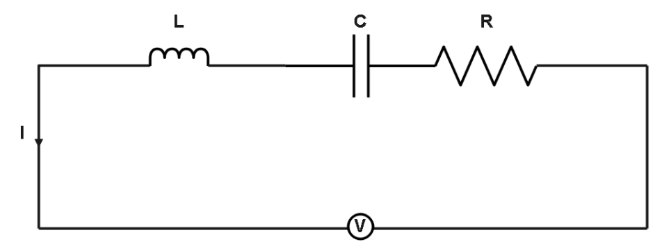
Resonance is the phenomenon in the circuit when the output of that electric circuit is maximum at one particular frequency. In an LCR circuit, this frequency is determined by the values of inductance, conductance, and resistance. If the inductor, capacitor and resistor are connected in series then the circuit is called a Series resonance circuit. But, if they are connected in parallel, then the circuit is called Parallel Resonance circuit.
In LCR series circuits,
As we know that at resonance,
${X_L} = {X_c}$
Where as
$ {X_L}{\text{ is the inductive reactance}} \\
{X_C}{\text{ is the capacitive reactance}} $
So, total reactance is ${X_T}$ which is,
${X_T} = {X_L} - {X_C}$
Which is Zero
$ \therefore Z = \sqrt {{{({X_{_L}} - {X_C})}^2} + {R^2}} \\
\Rightarrow Z = \sqrt {{R^2}} \\
\Rightarrow Z = R $
$Z$ is impedance.
$R$ is resistance
So, the relation between impedance of a series LCR circuit and its resistance R at resonance is $Z = R$
Additional Information:
Inductor (L): It is a two-terminal passive electrical component that opposes sudden changes in current. It is used to store energy in the form of magnetic energy when electricity is applied to it.
Capacitor(C): A capacitor is a two-terminal electrical device that can store energy in the form of an electric charge. Capacitors include two electrical conductors, which are separated by a distance.
Resistor(R): A resistor is a passive two-terminal electrical component that implements electrical resistance as a circuit element. In electronic circuits, resistors are used to reduce current flow, adjust signal levels, to divide voltages, bias active elements, and terminate transmission lines, among other uses.
Note: Impedance can be minimized by making the applied AC frequency equal to the resonant frequency of the LCR circuit. There is no difference between an RLC circuit and an LCR circuit except for the order of the symbol represented in the circuit diagram.
Complete step-by-step solution:
Resonance is the phenomenon in the circuit when the output of that electric circuit is maximum at one particular frequency. In an LCR circuit, this frequency is determined by the values of inductance, conductance, and resistance. If the inductor, capacitor and resistor are connected in series then the circuit is called a Series resonance circuit. But, if they are connected in parallel, then the circuit is called Parallel Resonance circuit.
In LCR series circuits,
As we know that at resonance,
${X_L} = {X_c}$
Where as
$ {X_L}{\text{ is the inductive reactance}} \\
{X_C}{\text{ is the capacitive reactance}} $
So, total reactance is ${X_T}$ which is,
${X_T} = {X_L} - {X_C}$
Which is Zero
$ \therefore Z = \sqrt {{{({X_{_L}} - {X_C})}^2} + {R^2}} \\
\Rightarrow Z = \sqrt {{R^2}} \\
\Rightarrow Z = R $
$Z$ is impedance.
$R$ is resistance
So, the relation between impedance of a series LCR circuit and its resistance R at resonance is $Z = R$
Additional Information:
Inductor (L): It is a two-terminal passive electrical component that opposes sudden changes in current. It is used to store energy in the form of magnetic energy when electricity is applied to it.
Capacitor(C): A capacitor is a two-terminal electrical device that can store energy in the form of an electric charge. Capacitors include two electrical conductors, which are separated by a distance.
Resistor(R): A resistor is a passive two-terminal electrical component that implements electrical resistance as a circuit element. In electronic circuits, resistors are used to reduce current flow, adjust signal levels, to divide voltages, bias active elements, and terminate transmission lines, among other uses.
Note: Impedance can be minimized by making the applied AC frequency equal to the resonant frequency of the LCR circuit. There is no difference between an RLC circuit and an LCR circuit except for the order of the symbol represented in the circuit diagram.
Recently Updated Pages
Master Class 12 Economics: Engaging Questions & Answers for Success
Master Class 12 Physics: Engaging Questions & Answers for Success
Master Class 12 English: Engaging Questions & Answers for Success
Master Class 12 Social Science: Engaging Questions & Answers for Success
Master Class 12 Maths: Engaging Questions & Answers for Success
Master Class 12 Business Studies: Engaging Questions & Answers for Success
Trending doubts
Which are the Top 10 Largest Countries of the World?
What are the major means of transport Explain each class 12 social science CBSE
Draw a labelled sketch of the human eye class 12 physics CBSE
Why cannot DNA pass through cell membranes class 12 biology CBSE
Differentiate between insitu conservation and exsitu class 12 biology CBSE
Draw a neat and well labeled diagram of TS of ovary class 12 biology CBSE