


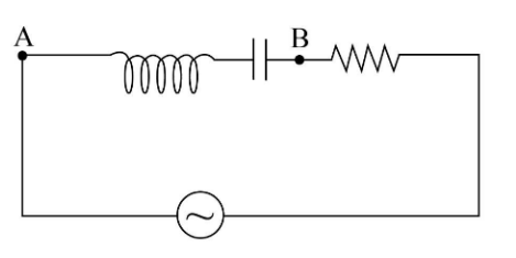
An inductor \[\left( {L = \dfrac{1}{{100\pi }}{\rm{H}}} \right)\], a capacitor \[\left( {C = \dfrac{1}{{500\pi }}{\rm{F}}} \right)\] and a resistance\[\left( {3\Omega } \right)\] is connected in series with an AC voltage source as shown in the figure. The voltage of the AC source is given as \[V = 10\cos \left( {100\pi t} \right){\rm{ Volt}}\]. What will be the potential difference between A and B?
(A) \[8\cos \left( {100\pi t - 127^\circ } \right){\rm{ Volt}}\]
(B) \[8\cos \left( {100\pi t - 53.13^\circ } \right){\rm{ Volt}}\]
(C) \[8\cos \left( {100\pi t - 37^\circ } \right){\rm{ Volt}}\]
(D) \[8\cos \left( {100\pi t + 37^\circ } \right){\rm{ Volt}}\]
Answer
606.3k+ views
Hint:We will write the expression for impedance of a given R-L-C circuit which gives us the relation between capacitive reactance, inductive reactance and resistance of the circuit. We will use the concept of voltage derived from Ohm’s law to write the final expression for the potential difference between A and B.
Complete step by step answer:
Given:
The inductance of the inductor is \[L = \dfrac{1}{{100\pi }}{\rm{H}}\].
The capacitance of the capacitor is \[C = \dfrac{1}{{500\pi }}{\rm{F}}\].
The resistance of the resistor is \[R = 3\Omega \].
The voltage of the AC source is \[V = 10\cos \left( {100\pi t} \right){\rm{ Volt}}\].
We know that the general form of the AC voltage is \[V = 100\cos \left( {\omega t} \right){\rm{ Volt}}\]. On comparing the given voltage of AC source with its general expression, we will get the value of frequency as below:
\[\omega = 100\pi {\rm{ Hz}}\]
Let us write the expression for impedance of the given L-C-R circuit.
\[Z = \sqrt {{{\left( {{X_C} - {X_L}} \right)}^2} + {R^2}} \]…...(1)
Here \[{X_C}\] is the capacitive reactance and \[{X_L}\] is the inductive reactive and R is the resistance of the given R-L-C circuit.
We can write the expression for capacitive reactance as below:
\[{X_C} = \dfrac{1}{{\omega C}}\]
On substituting \[\dfrac{1}{{500\pi }}{\rm{F}}\] for C and \[100\pi {\rm{ Hz}}\] for \[\omega \] in the above expression, we get:
\[
{X_C} = \dfrac{1}{{\left( {100\pi {\rm{ Hz}}} \right)\left( {\dfrac{1}{{500\pi }}{\rm{F}}} \right)}}\\
= 5\Omega
\]
We can also write the expression for inductive reactance as below:
\[{X_L} = \omega L\]
On substituting \[\dfrac{1}{{100\pi }}{\rm{H}}\] for L and \[100\pi {\rm{ Hz}}\] for \[\omega \] in the above expression, we get:
\[
{X_L} = \left( {100\pi {\rm{ Hz}}} \right)\left( {\dfrac{1}{{100\pi }}{\rm{H}}} \right)\\
= 1\Omega
\]
On substituting \[5\Omega \] for \[{X_C}\], \[1\Omega \] for \[{X_L}\] and \[3\Omega \] for R in equation (1), we get:
\[
Z = \sqrt {{{\left( {5\Omega - 1\Omega } \right)}^2} + 3{\Omega ^2}} \\
= 5\Omega
\]
We can write the expression for phase difference as below:
\[\phi = {\tan ^{ - 1}}\left( {\dfrac{{{X_C} - {X_L}}}{R}} \right)\]
On substituting \[5\Omega \] for \[{X_C}\], \[1\Omega \] for \[{X_L}\] and \[3\Omega \] for R in the above expression, we get:
\[
\phi = {\tan ^{ - 1}}\left( {\dfrac{{5\Omega - 1\Omega }}{{3\Omega }}} \right)\\
= 53.13^\circ
\]
We can write the expression for the current of the given circuit as the ratio of voltage and impedance of the circuit.
\[I = \dfrac{V}{Z}\]
We know that the phase difference is the lag of current with a potential difference so that we can substitute \[10\cos \left( {100\pi t - \phi } \right){\rm{ Volt}}\] for V and \[5\Omega \] for Z in the above expression.
\[
I = \dfrac{{10\cos \left( {100\pi t - \phi } \right){\rm{ Volt}}}}{{5\Omega }}\\
= 2\cos \left( {100\pi t - \phi } \right){\rm{ A}}
\]
Now we will substitute \[53.13^\circ \] for \[\phi \] in the above expression.
\[I = 2\cos \left( {100\pi t - 53.13^\circ } \right){\rm{ A}}\]
We can write the impedance between point A and point B as the difference between capacitive and inductive reactance.
\[R' = {X_C} - {X_L}\]
On substituting \[5\Omega \] for \[{X_C}\] and \[1\Omega \] for \[{X_L}\] in the above expression, we get:
\[
R' = 5\Omega - 1\Omega \\
= 4\Omega
\]
The potential difference between point A and point B is given by:
\[V' = IR'\]
On substituting \[4\Omega \] for R’ and \[2\cos \left( {100\pi t - 53.13^\circ } \right){\rm{ A}}\] for I in the above expression, we get:
\[
V' = \left[ {2\cos \left( {100\pi t - 53.13^\circ } \right){\rm{ A}}} \right]\left[ {4\Omega } \right]\\
= 8\cos \left( {100\pi t - 53.13^\circ } \right){\rm{ Volt}}
\]
Therefore, the potential difference between A and B is \[8\cos \left( {100\pi t - 53.13^\circ } \right){\rm{ Volt}}\], and option (B) is correct.
Note: Do not forget to subtract the phase difference from potential difference while writing the expression for current through the given circuit. The unit of inductive reactance, capacitive reactance is the same as the unit of resistance, so do not confuse with that.
Recently Updated Pages
Master Class 12 Business Studies: Engaging Questions & Answers for Success
Master Class 12 Biology: Engaging Questions & Answers for Success
Master Class 12 Chemistry: Engaging Questions & Answers for Success
Class 12 Question and Answer - Your Ultimate Solutions Guide
Master Class 11 Social Science: Engaging Questions & Answers for Success
Master Class 11 English: Engaging Questions & Answers for Success
Trending doubts
Which are the Top 10 Largest Countries of the World?
Draw a labelled sketch of the human eye class 12 physics CBSE
Name the crygenes that control cotton bollworm and class 12 biology CBSE
Differentiate between homogeneous and heterogeneous class 12 chemistry CBSE
Ribosomal RNA is actively synthesised in A Nucleoplasm class 12 biology CBSE
How many molecules of ATP and NADPH are required information class 12 biology CBSE