


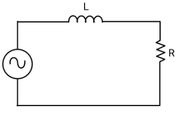
An inductor and a resistor in series are connected to an A.C. supply of variable frequency. As the frequency of the source is increased, the phase angle between current and the potential difference across $L$ will
A. First increase and then decrease
B. First decrease and then increase
C. Go on decreasing
D. Go on increasing
Answer
590.1k+ views
Hint: Here we have to find a relation between the frequency of the applied AC source and the phase angle between the current and the potential difference across L, so it will help to find the variation in phase as frequency is increased. To get this, use the vector method.
Complete step by step answer:
In vector method, the resistance is represented by a vector of magnitude $R$ along the x-axis and the reactance of the inductor is represented by a vector of magnitude \[{X_L}\] along the negative y-axis which will be lagging behind the resistance vector by a phase of $\dfrac{\pi }{2}$. The vector sum gives the impedance of the circuit and the phase angle.
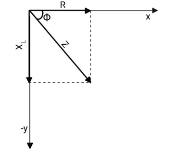
From here, you can find the tangent of the phase angle $\phi $
$\tan \phi = \dfrac{{{X_L}}}{R}$
${X_L}$ is the reactance of inductor and is given as ${X_L} = \omega L$, where $\omega $ is the angular frequency of the applied voltage and $L$ is the inductance of the inductor.
Now, $\tan \phi = \dfrac{{\omega L}}{R}$.
If the frequency of the applied source increases, the tangent of the phase angle increases. Implying that the phase angle between the current and the potential difference will also increase.
Hence, as the frequency of the source is increased, the phase angle between current and the potential difference across $L$ will go on increasing.Therefore,option (D) is correct.
Additional information:
In the above case, the current is given as $I = \dfrac{{{V_0}}}{{\sqrt {\left( {{R^2} + {X_L}^2} \right)} }}\sin \left( {\omega t - \phi } \right)$, here ${V_0}$is the peak voltage. The applied voltage is given by $V = {V_0}\sin \omega t$. From the equations of current and voltage, we conclude that in an LR circuit, the current lags the voltage.
In case of RC circuit, the tangent of the phase angle is given as $\tan \phi = \dfrac{{ - {X_C}}}{R}$, as one can see that the phase angle will come out to be negative. Now, as $I = \dfrac{{{V_0}}}{{\sqrt {\left( {{R^2} + {X_L}^2} \right)} }}\sin \left( {\omega t - \phi } \right)$, the phase angle will nullify the negative sign and the overall phase will be positive, meaning the voltage will lag the current.
Note: Always remember the vector representation. The resistance is represented along the x-axis, reactance of inductor along negative y-axis and reactance of capacitor along positive y-axis. This will help you in solving many questions related to alternating current.
Complete step by step answer:
In vector method, the resistance is represented by a vector of magnitude $R$ along the x-axis and the reactance of the inductor is represented by a vector of magnitude \[{X_L}\] along the negative y-axis which will be lagging behind the resistance vector by a phase of $\dfrac{\pi }{2}$. The vector sum gives the impedance of the circuit and the phase angle.
From here, you can find the tangent of the phase angle $\phi $
$\tan \phi = \dfrac{{{X_L}}}{R}$
${X_L}$ is the reactance of inductor and is given as ${X_L} = \omega L$, where $\omega $ is the angular frequency of the applied voltage and $L$ is the inductance of the inductor.
Now, $\tan \phi = \dfrac{{\omega L}}{R}$.
If the frequency of the applied source increases, the tangent of the phase angle increases. Implying that the phase angle between the current and the potential difference will also increase.
Hence, as the frequency of the source is increased, the phase angle between current and the potential difference across $L$ will go on increasing.Therefore,option (D) is correct.
Additional information:
In the above case, the current is given as $I = \dfrac{{{V_0}}}{{\sqrt {\left( {{R^2} + {X_L}^2} \right)} }}\sin \left( {\omega t - \phi } \right)$, here ${V_0}$is the peak voltage. The applied voltage is given by $V = {V_0}\sin \omega t$. From the equations of current and voltage, we conclude that in an LR circuit, the current lags the voltage.
In case of RC circuit, the tangent of the phase angle is given as $\tan \phi = \dfrac{{ - {X_C}}}{R}$, as one can see that the phase angle will come out to be negative. Now, as $I = \dfrac{{{V_0}}}{{\sqrt {\left( {{R^2} + {X_L}^2} \right)} }}\sin \left( {\omega t - \phi } \right)$, the phase angle will nullify the negative sign and the overall phase will be positive, meaning the voltage will lag the current.
Note: Always remember the vector representation. The resistance is represented along the x-axis, reactance of inductor along negative y-axis and reactance of capacitor along positive y-axis. This will help you in solving many questions related to alternating current.
Recently Updated Pages
Master Class 12 Social Science: Engaging Questions & Answers for Success
Master Class 12 Physics: Engaging Questions & Answers for Success
Master Class 12 Maths: Engaging Questions & Answers for Success
Master Class 12 Economics: Engaging Questions & Answers for Success
Master Class 12 Chemistry: Engaging Questions & Answers for Success
Master Class 12 Business Studies: Engaging Questions & Answers for Success
Trending doubts
Explain the structure of megasporangium class 12 biology CBSE
What are the major means of transport Explain each class 12 social science CBSE
How many chromosomes are found in human ovum a 46 b class 12 biology CBSE
The diagram of the section of a maize grain is given class 12 biology CBSE
No of 5 membered ring in left Caleft EDTA right right2 class 12 chemistry CBSE
How many 176Omega resistors in parallel are required class 12 physics CBSE