


An inductor $20mH$, a capacitor $50\mu F$ and a resistor $40\Omega $ are connected in series across a source of emf $V=10\sin \left( 340t \right)$. The power loss in AC circuit is:
$\begin{align}
& \text{A}\text{. }0.51W \\
& \text{B}\text{. }0.67W \\
& \text{C}\text{. }0.76W \\
& \text{D}\text{. }0.89W \\
\end{align}$
Answer
596.4k+ views
Hint: When the components, inductor, capacitor, and resistor are connected in series in a circuit, the average power dissipated can be expressed in terms of the RMS voltage and current. We will find the expression for power dissipation in a series LCR circuit using the equation of impedance in an AC circuit.
Formula used:
$P=\dfrac{{{E}^{2}}R}{\sqrt{{{R}^{2}}+{{\left( \omega L-\dfrac{1}{\omega C} \right)}^{2}}}}$
Complete step by step answer:
An RLC circuit is an electrical circuit which consists of a resistor $(R)$, an inductor $(L)$, and a capacitor $(C)$ connected in series or in parallel.
Series RLC circuit:
In this circuit, the three components are all connected in series with the voltage source.
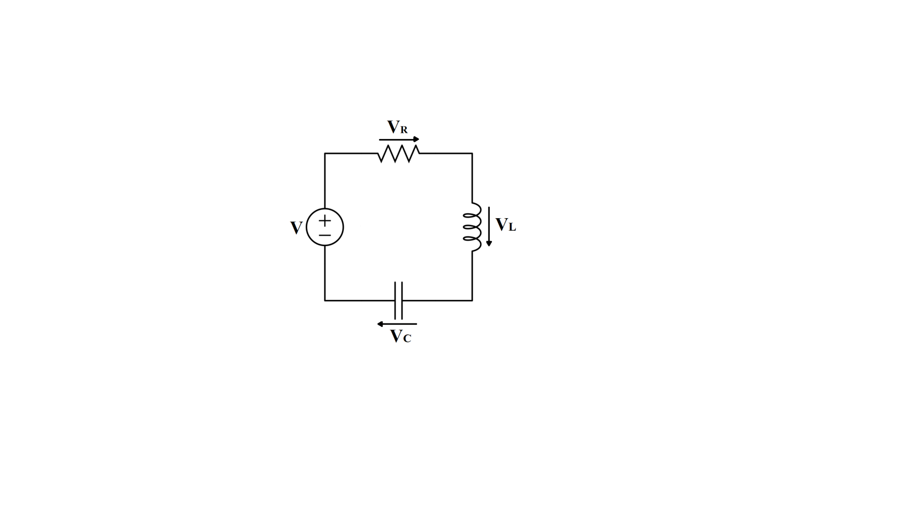
From KVL,
${{V}_{R}}+{{V}_{L}}+{{V}_{C}}=V(t)$
Where,
${{V}_{R}}$ is the voltage across $R$
${{V}_{L}}$ is the voltage across $L$
${{V}_{C}}$ is the voltage across $C$
$V(t)$ is the time varying voltage from the source
We are given,
Inductance, $L=20mH$
Capacitance, $C=50\mu F$
Resistance, $R=40\Omega $
The EMF of the electrical circuit is $E$
The impedance of the series LCR circuit is given as,
\[Z=\sqrt{{{R}^{2}}+{{\left( \omega L-\dfrac{1}{\omega C} \right)}^{2}}}\]
The power factor in a series LCR circuit is given as,
$\cos \phi =\dfrac{R}{\left| Z \right|}$
The power dissipated in the circuit is given as,
$P={{V}_{rms}}{{I}_{rms}}\cos \phi $
We have,
${{V}_{rms}}=E$
${{I}_{rms}}=\dfrac{E}{\left| Z \right|}$
$\cos \phi =\dfrac{R}{\left| Z \right|}$
Therefore,
$P=E\times \dfrac{E}{\left| Z \right|}\times \dfrac{R}{\left| Z \right|}$
Put \[Z=\sqrt{{{R}^{2}}+{{\left( \omega L-\dfrac{1}{\omega C} \right)}^{2}}}\]
$P=\dfrac{{{E}^{2}}R}{\sqrt{{{R}^{2}}+{{\left( \omega L-\dfrac{1}{\omega C} \right)}^{2}}}}$
Thus,
Power dissipated in the series LCR circuit is given as,
$P=\dfrac{{{E}^{2}}R}{\sqrt{{{R}^{2}}+{{\left( \omega L-\dfrac{1}{\omega C} \right)}^{2}}}}$
We are given that an inductor $20mH$, a capacitor $50\mu F$ and a resistor $40\Omega $ are connected in series across a source of EMF $V=10\sin \left( 340t \right)$.
EMF of the circuit, $V=10\sin \left( 340t \right)$
Impedance of the circuit is given as,
\[Z=\sqrt{{{R}^{2}}+{{\left( {{X}_{L}}-{{X}_{C}} \right)}^{2}}}\]
$\begin{align}
& {{X}_{L}}=\omega L \\
& {{X}_{C}}=\dfrac{1}{\omega C} \\
\end{align}$
Given values,
$L=20mH$
$C=50\mu F$
$R=40\Omega $
$\omega =340$
We get,
$\begin{align}
& Z=\sqrt{{{\left( 40 \right)}^{2}}+{{\left( 340\times 20\times {{10}^{-3}}-\dfrac{1}{340\times 50\times {{10}^{-6}}} \right)}^{2}}} \\
& \Rightarrow Z=\sqrt{1600+2704} \\
& \Rightarrow Z=\sqrt{4304} \\
& \Rightarrow Z=65.60\Omega \\
\end{align}$
Power loss in AC circuit is given as,
\[\begin{align}
& {{P}_{avg}}={{\left( {{I}_{V}} \right)}^{2}}R \\
& {{P}_{avg}}={{\left[ \dfrac{{{E}_{V}}}{Z} \right]}^{2}}R \\
\end{align}\]
Putting the values,
$\begin{align}
& {{E}_{V}}=10V \\
& R=40\Omega \\
& {{Z}^{2}}=4304{{\Omega }^{2}} \\
\end{align}$
${{P}_{avg}}={{\left( \dfrac{10}{\sqrt{2}} \right)}^{2}}\times 40\times \left[ \dfrac{1}{4304} \right]$
${{P}_{avg}}\approx 0.51W$
Hence, the correct option is A.
Note:
Root mean square voltage (RMS) is a method of denoting voltage sine waveform as an equivalent voltage which represents the DC voltage value that will produce the same heating effect, or power dissipation, in circuit as the AC voltage. We use RMS voltage and RMS current to calculate the average power in a circuit to get meaningful power values.
Formula used:
$P=\dfrac{{{E}^{2}}R}{\sqrt{{{R}^{2}}+{{\left( \omega L-\dfrac{1}{\omega C} \right)}^{2}}}}$
Complete step by step answer:
An RLC circuit is an electrical circuit which consists of a resistor $(R)$, an inductor $(L)$, and a capacitor $(C)$ connected in series or in parallel.
Series RLC circuit:
In this circuit, the three components are all connected in series with the voltage source.
From KVL,
${{V}_{R}}+{{V}_{L}}+{{V}_{C}}=V(t)$
Where,
${{V}_{R}}$ is the voltage across $R$
${{V}_{L}}$ is the voltage across $L$
${{V}_{C}}$ is the voltage across $C$
$V(t)$ is the time varying voltage from the source
We are given,
Inductance, $L=20mH$
Capacitance, $C=50\mu F$
Resistance, $R=40\Omega $
The EMF of the electrical circuit is $E$
The impedance of the series LCR circuit is given as,
\[Z=\sqrt{{{R}^{2}}+{{\left( \omega L-\dfrac{1}{\omega C} \right)}^{2}}}\]
The power factor in a series LCR circuit is given as,
$\cos \phi =\dfrac{R}{\left| Z \right|}$
The power dissipated in the circuit is given as,
$P={{V}_{rms}}{{I}_{rms}}\cos \phi $
We have,
${{V}_{rms}}=E$
${{I}_{rms}}=\dfrac{E}{\left| Z \right|}$
$\cos \phi =\dfrac{R}{\left| Z \right|}$
Therefore,
$P=E\times \dfrac{E}{\left| Z \right|}\times \dfrac{R}{\left| Z \right|}$
Put \[Z=\sqrt{{{R}^{2}}+{{\left( \omega L-\dfrac{1}{\omega C} \right)}^{2}}}\]
$P=\dfrac{{{E}^{2}}R}{\sqrt{{{R}^{2}}+{{\left( \omega L-\dfrac{1}{\omega C} \right)}^{2}}}}$
Thus,
Power dissipated in the series LCR circuit is given as,
$P=\dfrac{{{E}^{2}}R}{\sqrt{{{R}^{2}}+{{\left( \omega L-\dfrac{1}{\omega C} \right)}^{2}}}}$
We are given that an inductor $20mH$, a capacitor $50\mu F$ and a resistor $40\Omega $ are connected in series across a source of EMF $V=10\sin \left( 340t \right)$.
EMF of the circuit, $V=10\sin \left( 340t \right)$
Impedance of the circuit is given as,
\[Z=\sqrt{{{R}^{2}}+{{\left( {{X}_{L}}-{{X}_{C}} \right)}^{2}}}\]
$\begin{align}
& {{X}_{L}}=\omega L \\
& {{X}_{C}}=\dfrac{1}{\omega C} \\
\end{align}$
Given values,
$L=20mH$
$C=50\mu F$
$R=40\Omega $
$\omega =340$
We get,
$\begin{align}
& Z=\sqrt{{{\left( 40 \right)}^{2}}+{{\left( 340\times 20\times {{10}^{-3}}-\dfrac{1}{340\times 50\times {{10}^{-6}}} \right)}^{2}}} \\
& \Rightarrow Z=\sqrt{1600+2704} \\
& \Rightarrow Z=\sqrt{4304} \\
& \Rightarrow Z=65.60\Omega \\
\end{align}$
Power loss in AC circuit is given as,
\[\begin{align}
& {{P}_{avg}}={{\left( {{I}_{V}} \right)}^{2}}R \\
& {{P}_{avg}}={{\left[ \dfrac{{{E}_{V}}}{Z} \right]}^{2}}R \\
\end{align}\]
Putting the values,
$\begin{align}
& {{E}_{V}}=10V \\
& R=40\Omega \\
& {{Z}^{2}}=4304{{\Omega }^{2}} \\
\end{align}$
${{P}_{avg}}={{\left( \dfrac{10}{\sqrt{2}} \right)}^{2}}\times 40\times \left[ \dfrac{1}{4304} \right]$
${{P}_{avg}}\approx 0.51W$
Hence, the correct option is A.
Note:
Root mean square voltage (RMS) is a method of denoting voltage sine waveform as an equivalent voltage which represents the DC voltage value that will produce the same heating effect, or power dissipation, in circuit as the AC voltage. We use RMS voltage and RMS current to calculate the average power in a circuit to get meaningful power values.
Recently Updated Pages
Master Class 12 Economics: Engaging Questions & Answers for Success
Master Class 12 Physics: Engaging Questions & Answers for Success
Master Class 12 English: Engaging Questions & Answers for Success
Master Class 12 Social Science: Engaging Questions & Answers for Success
Master Class 12 Maths: Engaging Questions & Answers for Success
Master Class 12 Business Studies: Engaging Questions & Answers for Success
Trending doubts
Which are the Top 10 Largest Countries of the World?
What are the major means of transport Explain each class 12 social science CBSE
Draw a labelled sketch of the human eye class 12 physics CBSE
Why cannot DNA pass through cell membranes class 12 biology CBSE
Differentiate between insitu conservation and exsitu class 12 biology CBSE
Draw a neat and well labeled diagram of TS of ovary class 12 biology CBSE