


A. State the working principle of a potentiometer. With the help of circuit diagrams explain how a potentiometer is used to compare the emfs of two primary cells. Obtain the required expression for comparing the emfs.
B. Write two possible causes for one sided deflection in a potentiometer experiment.
Answer
619.2k+ views
Hint: Remember that a potentiometer wire has a uniform area of cross-section. Think of what this would do to the resistance of the wire per unit length if a constant current passes through it. In other words, the resistance of the wire would remain the same throughout, so this should give you the relation between the voltage drop across the wire and the length of the wire. This will be the principle of working on the potentiometer.
As for the second part, recall that a galvanometer deflects from its null point when it detects a voltage drop due to some current passing through it. To this end, think of different sources from the circuit for the galvanometer to be reading a finite voltage
Formula used:
Ohm’s law: $V = IR$. Where V is the potential difference across the wire, I is the current flowing through the wire and R is the resistance of the wire.
The ratio of the emfs $e_1$ and $e_2$ of the two cells connected to the potentiometer is $\dfrac{e_1}{e_2} = \dfrac{l_1}{l_2}$, where $l_1$ and $l_2$ are the distances of the balance points from the end of the potentiometer wire that is connected to the $+ve$ terminal of the battery.
Complete step by step answer:
Let us begin by understanding what a potentiometer is and what principle is behind its working.
A potentiometer is an instrument used for accurately measuring the emf or the potential difference across a circuit by comparing it with a known voltage. It is designed in such a way that it balances the emf against the potential difference produced by passing a known current through a known variable resistance. Let us look at the construction of a potentiometer.
The main part of the potentiometer is the wire $ab$ which is a wire with a uniform cross-sectional area. This wire is fitted along with a metre scale on a wooden board. Both the ends of the wire are connected to terminals $a$ and $b$. A battery $B$, an ammeter $A$, a rheostat $Rh$ and a key $K$ are connected in series with the wire $ab$. The circuit containing $B$, $A$, $Rh$ and $K$ is called the auxiliary circuit.
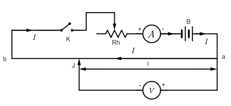
A. The potentiometer works on the principle of uniform resistance. Since the wire $ab$ has a uniform area of cross-section, its resistance per unit length at every point is the same. This can be quantified as follows:
Let $I$ be the current flowing through the wire $ab$, $r$ be the resistance per unit length of the wire $ab$, and $e$, which is the electromotive force, be the potential difference across unit length of the wire.
From Ohm’s law we can deduce that $e = Ir$
Now, if the current $I$ through the wire does not change, then $e = $ constant, since r is assumed to be the same throughout.
If V is the fall of potential across a length $l$ of the wire, then $V = el$, and since $e$ is a constant $\Rightarrow V \propto l$
From this, we infer that the potential difference between any two points of a wire of uniform area of cross-section is directly proportional to the length of the wire between these points, provided that the current through the wire remains constant.
This is the principle of a potentiometer. So, from the circuit, we record the readings of $V$ on the voltmeter for different positions of the contact which is the jockey $J$ that can be read off from the metre scale. A graph plotted between $V$ and $l$ would be a straight line passing through the origin, which means that the resistance throughout the length of the wire remains constant.
One of the applications of a potentiometer is that it is used to compare the emfs of two cells. It is a simple and versatile application, so let us now look at how this is done.
In addition to the potentiometer circuit and the auxiliary circuit, we now introduce the two cells whose emfs require comparison.
We connect the two cells to the circuit as shown in the diagram.
The positive terminal of the cells are connected to the end $a$ and the negative terminal of the cells are connected to one end of the galvanometer in turns. The other end of the galvanometer is connected to the jockey $J$ which acts as a contact point that slides along the wire $ab$. Note that when terminals 1 and 3 are connected, cell $e_1$ is in the circuit and when 2 and 3 are connected, cell $e_2$ is in the circuit.
We first connect $e_1$ into the circuit and slide the jockey along the wire $ab$ until we arrive at a point where the galvanometer shows no deflection. Let this point be at a distance $l_1$ from point $a$. Now we disconnect $e_1$ from terminal $3$ of the galvanometer and connect the terminals $2$ and $3$ to bring cell $e_2$ into the circuit. Let the point of no deflection for $e_2$ be $l_2$ from end $a$.
Now, from the working principle of the potentiometer that we derived, we can establish that:
$e_1 \propto l_1$ and $e_2 \propto l_2$
$\Rightarrow \dfrac{e_1}{e_2} = \dfrac{l_1}{l_2}$
This way we can compare the emfs of two cells using a potentiometer.
B. Two possible causes for a one-sided deflection in the galvanometer of a potentiometer experiment could be:
The potential difference between $a$ and $b$ or the emf of the battery $B$ in the main circuit may not be greater than the emf of the cells whose emf are to be compared.
The positive terminals of the cells and the battery used in the circuit may not be connected to the same end of the potentiometer wire
A good way to verify the surety of your circuit connection will be to place the jockey at points $a$ and $b$ which are the ends of the potentiometer wire, and see if you get a null-point or a one-sided deflection on the galvanometer. If you do not get a null-point, it means that your circuit connections may be wrong or they may not be tight enough. Also ensure that no wires are broken.
Note:
In case of potentiometers we always look out for the null point. But it is important to have a clear understanding of why we do so. At the balance point, or the null point, no current flows through the cell. This means that the internal resistance of the cell has no effect on the measurement of our emf. Since we are able to measure the emf of the cell without drawing any current from it, we can consider the potentiometer to be an ideal voltmeter.
Also, remember that if the arrangement is not balanced there will be a potential drop across the galvanometer which is indicated by its deflection. So, when the galvanometer shows no deflection and is rested on the null point, the potential difference of the wire between the $+ve$ end of the battery and the jockey becomes equal to the emf of the cell, which is what we ultimately require.
As for the second part, recall that a galvanometer deflects from its null point when it detects a voltage drop due to some current passing through it. To this end, think of different sources from the circuit for the galvanometer to be reading a finite voltage
Formula used:
Ohm’s law: $V = IR$. Where V is the potential difference across the wire, I is the current flowing through the wire and R is the resistance of the wire.
The ratio of the emfs $e_1$ and $e_2$ of the two cells connected to the potentiometer is $\dfrac{e_1}{e_2} = \dfrac{l_1}{l_2}$, where $l_1$ and $l_2$ are the distances of the balance points from the end of the potentiometer wire that is connected to the $+ve$ terminal of the battery.
Complete step by step answer:
Let us begin by understanding what a potentiometer is and what principle is behind its working.
A potentiometer is an instrument used for accurately measuring the emf or the potential difference across a circuit by comparing it with a known voltage. It is designed in such a way that it balances the emf against the potential difference produced by passing a known current through a known variable resistance. Let us look at the construction of a potentiometer.
The main part of the potentiometer is the wire $ab$ which is a wire with a uniform cross-sectional area. This wire is fitted along with a metre scale on a wooden board. Both the ends of the wire are connected to terminals $a$ and $b$. A battery $B$, an ammeter $A$, a rheostat $Rh$ and a key $K$ are connected in series with the wire $ab$. The circuit containing $B$, $A$, $Rh$ and $K$ is called the auxiliary circuit.
A. The potentiometer works on the principle of uniform resistance. Since the wire $ab$ has a uniform area of cross-section, its resistance per unit length at every point is the same. This can be quantified as follows:
Let $I$ be the current flowing through the wire $ab$, $r$ be the resistance per unit length of the wire $ab$, and $e$, which is the electromotive force, be the potential difference across unit length of the wire.
From Ohm’s law we can deduce that $e = Ir$
Now, if the current $I$ through the wire does not change, then $e = $ constant, since r is assumed to be the same throughout.
If V is the fall of potential across a length $l$ of the wire, then $V = el$, and since $e$ is a constant $\Rightarrow V \propto l$
From this, we infer that the potential difference between any two points of a wire of uniform area of cross-section is directly proportional to the length of the wire between these points, provided that the current through the wire remains constant.
This is the principle of a potentiometer. So, from the circuit, we record the readings of $V$ on the voltmeter for different positions of the contact which is the jockey $J$ that can be read off from the metre scale. A graph plotted between $V$ and $l$ would be a straight line passing through the origin, which means that the resistance throughout the length of the wire remains constant.
One of the applications of a potentiometer is that it is used to compare the emfs of two cells. It is a simple and versatile application, so let us now look at how this is done.
In addition to the potentiometer circuit and the auxiliary circuit, we now introduce the two cells whose emfs require comparison.
We connect the two cells to the circuit as shown in the diagram.
The positive terminal of the cells are connected to the end $a$ and the negative terminal of the cells are connected to one end of the galvanometer in turns. The other end of the galvanometer is connected to the jockey $J$ which acts as a contact point that slides along the wire $ab$. Note that when terminals 1 and 3 are connected, cell $e_1$ is in the circuit and when 2 and 3 are connected, cell $e_2$ is in the circuit.
We first connect $e_1$ into the circuit and slide the jockey along the wire $ab$ until we arrive at a point where the galvanometer shows no deflection. Let this point be at a distance $l_1$ from point $a$. Now we disconnect $e_1$ from terminal $3$ of the galvanometer and connect the terminals $2$ and $3$ to bring cell $e_2$ into the circuit. Let the point of no deflection for $e_2$ be $l_2$ from end $a$.
Now, from the working principle of the potentiometer that we derived, we can establish that:
$e_1 \propto l_1$ and $e_2 \propto l_2$
$\Rightarrow \dfrac{e_1}{e_2} = \dfrac{l_1}{l_2}$
This way we can compare the emfs of two cells using a potentiometer.
B. Two possible causes for a one-sided deflection in the galvanometer of a potentiometer experiment could be:
The potential difference between $a$ and $b$ or the emf of the battery $B$ in the main circuit may not be greater than the emf of the cells whose emf are to be compared.
The positive terminals of the cells and the battery used in the circuit may not be connected to the same end of the potentiometer wire
A good way to verify the surety of your circuit connection will be to place the jockey at points $a$ and $b$ which are the ends of the potentiometer wire, and see if you get a null-point or a one-sided deflection on the galvanometer. If you do not get a null-point, it means that your circuit connections may be wrong or they may not be tight enough. Also ensure that no wires are broken.
Note:
In case of potentiometers we always look out for the null point. But it is important to have a clear understanding of why we do so. At the balance point, or the null point, no current flows through the cell. This means that the internal resistance of the cell has no effect on the measurement of our emf. Since we are able to measure the emf of the cell without drawing any current from it, we can consider the potentiometer to be an ideal voltmeter.
Also, remember that if the arrangement is not balanced there will be a potential drop across the galvanometer which is indicated by its deflection. So, when the galvanometer shows no deflection and is rested on the null point, the potential difference of the wire between the $+ve$ end of the battery and the jockey becomes equal to the emf of the cell, which is what we ultimately require.
Recently Updated Pages
Master Class 12 Business Studies: Engaging Questions & Answers for Success
Master Class 12 Biology: Engaging Questions & Answers for Success
Master Class 12 Chemistry: Engaging Questions & Answers for Success
Class 12 Question and Answer - Your Ultimate Solutions Guide
Master Class 11 Social Science: Engaging Questions & Answers for Success
Master Class 11 English: Engaging Questions & Answers for Success
Trending doubts
Which are the Top 10 Largest Countries of the World?
Draw a labelled sketch of the human eye class 12 physics CBSE
Name the crygenes that control cotton bollworm and class 12 biology CBSE
Differentiate between homogeneous and heterogeneous class 12 chemistry CBSE
Ribosomal RNA is actively synthesised in A Nucleoplasm class 12 biology CBSE
How many molecules of ATP and NADPH are required information class 12 biology CBSE