


(a) State Kirchhoff’s rules for an electric network Using Kirchhoff’s rules , obtain the balance condition in terms of the resistance of four arms of Wheatstone bridge
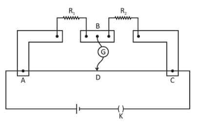
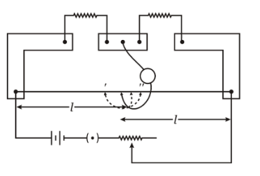
(b) In the meter bridge set up, shown in the figure, the null point “ \[D\] “ is obtained at a distance of \[40\,{\text{cm}}\] from end \[A\] of the meter bridge wire. If a resistance of \[\Omega \] is connected in series with \[{R_1}\] null point is obtained at \[AD = 60\,{\text{cm}}\] . Calculate the values of \[{R_1}\] and \[{R_2}\].
Answer
597k+ views
Hint:This law states the conservation of charge at any point in an electrical circuit. To find the resistance of the wire we will have to apply Kirchhoff’s current law. We will equate the currents at any point equal to zero. After that we will apply Kirchhoff’s voltage law. At null point, the ratio of the resistances on the either becomes equal. We will manipulate accordingly and find the result.
Complete step by step answer:
(a) We apply Kirchhoff’s law in complex networks to find current flows across various branches.
First law: Zero is the algebraic sum of currents that intersect at a point. I.e. \[\sum {i = 0} \].Considering the outward direction of the current as positive and inward as negative in the given circuit, then at point \[F\]. According to Kirchhoff’s first law, at point \[F\].
So, \[{I_1} + {I_2} = {I_3}\].
Second law: the algebraic sum of the product of resistance and the related current in the various branches in the closed mesh of electrical conductors is equal to the total e.m.f applied in the closed mesh.
\[\sum {IR = \sum E } \]
The condition for null deflection in a Wheatstone bridge is now found using Kirchhoff's law.
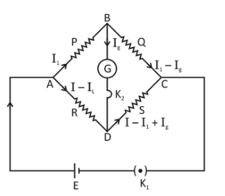
In order to form a closed circuit, four resistors \[P\], \[Q\], \[R\] and \[S\] are coupled end to end. Such tight networks of conductors create a closed circuit. This near conductor network is known as the bridge of Wheatstone. A battery is linked between any pair of opposite junctions, say \[A\] & \[C\], and a galvanometer is connected between the other pair of opposite junctions. We allocated the current flow from the logical consideration in the various divisions.
\[\dfrac{P}{Q} = \dfrac{R}{S}\]
Giving: \[G\] is the Galvanometer resistance.
Let \[{i_1}\],\[{i_2}\],\[{i_3}\],\[{i_4}\] & \[{i_g}\] be the current flowing through the resistance branches \[P\] , \[Q\] , \[R\] , \[S\] and \[G\] respectively.
By applying Kirchhoff’s first law,
At the point \[C\],
$\sum {i = 0} \\
\Rightarrow i - {i_1} - {i_2} = 0 \\$
\[ \Rightarrow {i_2} = i - {i_1}\] …… (1)
Similarly,
\[{i_3} = {i_1} - {i_g}\] ….. (2)
\[\Rightarrow{i_4} = i - {i_1} + {i_g}\] …… (3)
By applying Kirchhoff’s second law,
For, \[CBDC\],
\[{i_1}P + {i_g}G - {i_2}R = 0\] \[\left( {P + Q} \right){i_1} + {i_g}G - iR = 0\]…… (4)
Similarly applying in same,
For, \[BADB\],
\[Q{i_3} - {i_g}G - {i_4}S = 0\] …… (5)
By putting the value of equations (2) and (5), we get,
\[{i_g} = \dfrac{{i\left( {RQ - SP} \right)}}{{G\left( {Q + S} \right) + \left( {Q + G + S} \right)\left( {P + R} \right)}}\] ….. (6)
From equation (6) we can find the current through the galvanometer. \[{i_g} = 0\] from equation (6) \[{i_g} = 0\] for null deflection only if the condition for null deflection is \[\left( {RQ - PS} \right) = 0\] or \[P/Q = R/S\]
(b) Given, \[AD = 40\], \[DC = 60\]
So,
\[\dfrac{{{R_1}}}{{{R_2}}} = \dfrac{{AD}}{{DC}}\]
\[ \Rightarrow \dfrac{{{R_1}}}{{{R_2}}} = \dfrac{{40}}{{60}}\] …… (1)
Also,
\[\dfrac{{{R_1} + 10}}{{{R_2}}} = \dfrac{{60}}{{40}}\] ….. (2)
Dividing both the equation we get,
\dfrac{{{R_1} + 10}}{{{R_1}}} = \dfrac{{60}}{{40}} \times \dfrac{{60}}{{40}} \\
$\Rightarrow \dfrac{{{R_1} + 10}}{{{R_1}}} = \dfrac{9}{4} \\
\Rightarrow {R_1} = \dfrac{{40}}{5} \\
\Rightarrow {R_1} = 8\,\Omega \\$
Now, from equation (1), we get:
$\dfrac{{{R_1}}}{{{R_2}}} = \dfrac{{40}}{{60}} \\
\Rightarrow \dfrac{8}{{{R_2}}} = \dfrac{{40}}{{60}} \\
\Rightarrow {R_2} = \dfrac{{48}}{4} \\
\therefore {R_2} = 12\,\Omega $
The value of \[{R_1}\]and \[{R_2}\]will be,\[{R_1} = 8\,\Omega \] and \[{R_2} = 12\,\Omega \].
Additional information:
Kirchhoff’s circuit laws: In the lumped element model of electrical circuits, Kirchhoff’s circuit laws are two equals that deal with the current and potential difference (commonly known as voltage). The German physicist Gustav Kirchhoff first identified them in \[1845\]. This made Georg Ohm’s work generalized and followed the work of James Clerk Maxwell. Widely used in electrical engineering, they are often referred to as the principles of Kirchhoff or simply the laws of Kirchhoff. In time and frequency domains, these laws can be applied and form the basis for network analysis.
Note:Remember that, to help us understand how current and voltage function inside a circuit, Kirchhoff’s laws are used. They can also be used to evaluate complex circuits that, using what you already know about series and parallel resistors, cannot be reduced to one equivalent resistance. It must be remembered this law tells about the conservation of charge.
Complete step by step answer:
(a) We apply Kirchhoff’s law in complex networks to find current flows across various branches.
First law: Zero is the algebraic sum of currents that intersect at a point. I.e. \[\sum {i = 0} \].Considering the outward direction of the current as positive and inward as negative in the given circuit, then at point \[F\]. According to Kirchhoff’s first law, at point \[F\].
So, \[{I_1} + {I_2} = {I_3}\].
Second law: the algebraic sum of the product of resistance and the related current in the various branches in the closed mesh of electrical conductors is equal to the total e.m.f applied in the closed mesh.
\[\sum {IR = \sum E } \]
The condition for null deflection in a Wheatstone bridge is now found using Kirchhoff's law.
In order to form a closed circuit, four resistors \[P\], \[Q\], \[R\] and \[S\] are coupled end to end. Such tight networks of conductors create a closed circuit. This near conductor network is known as the bridge of Wheatstone. A battery is linked between any pair of opposite junctions, say \[A\] & \[C\], and a galvanometer is connected between the other pair of opposite junctions. We allocated the current flow from the logical consideration in the various divisions.
\[\dfrac{P}{Q} = \dfrac{R}{S}\]
Giving: \[G\] is the Galvanometer resistance.
Let \[{i_1}\],\[{i_2}\],\[{i_3}\],\[{i_4}\] & \[{i_g}\] be the current flowing through the resistance branches \[P\] , \[Q\] , \[R\] , \[S\] and \[G\] respectively.
By applying Kirchhoff’s first law,
At the point \[C\],
$\sum {i = 0} \\
\Rightarrow i - {i_1} - {i_2} = 0 \\$
\[ \Rightarrow {i_2} = i - {i_1}\] …… (1)
Similarly,
\[{i_3} = {i_1} - {i_g}\] ….. (2)
\[\Rightarrow{i_4} = i - {i_1} + {i_g}\] …… (3)
By applying Kirchhoff’s second law,
For, \[CBDC\],
\[{i_1}P + {i_g}G - {i_2}R = 0\] \[\left( {P + Q} \right){i_1} + {i_g}G - iR = 0\]…… (4)
Similarly applying in same,
For, \[BADB\],
\[Q{i_3} - {i_g}G - {i_4}S = 0\] …… (5)
By putting the value of equations (2) and (5), we get,
\[{i_g} = \dfrac{{i\left( {RQ - SP} \right)}}{{G\left( {Q + S} \right) + \left( {Q + G + S} \right)\left( {P + R} \right)}}\] ….. (6)
From equation (6) we can find the current through the galvanometer. \[{i_g} = 0\] from equation (6) \[{i_g} = 0\] for null deflection only if the condition for null deflection is \[\left( {RQ - PS} \right) = 0\] or \[P/Q = R/S\]
(b) Given, \[AD = 40\], \[DC = 60\]
So,
\[\dfrac{{{R_1}}}{{{R_2}}} = \dfrac{{AD}}{{DC}}\]
\[ \Rightarrow \dfrac{{{R_1}}}{{{R_2}}} = \dfrac{{40}}{{60}}\] …… (1)
Also,
\[\dfrac{{{R_1} + 10}}{{{R_2}}} = \dfrac{{60}}{{40}}\] ….. (2)
Dividing both the equation we get,
\dfrac{{{R_1} + 10}}{{{R_1}}} = \dfrac{{60}}{{40}} \times \dfrac{{60}}{{40}} \\
$\Rightarrow \dfrac{{{R_1} + 10}}{{{R_1}}} = \dfrac{9}{4} \\
\Rightarrow {R_1} = \dfrac{{40}}{5} \\
\Rightarrow {R_1} = 8\,\Omega \\$
Now, from equation (1), we get:
$\dfrac{{{R_1}}}{{{R_2}}} = \dfrac{{40}}{{60}} \\
\Rightarrow \dfrac{8}{{{R_2}}} = \dfrac{{40}}{{60}} \\
\Rightarrow {R_2} = \dfrac{{48}}{4} \\
\therefore {R_2} = 12\,\Omega $
The value of \[{R_1}\]and \[{R_2}\]will be,\[{R_1} = 8\,\Omega \] and \[{R_2} = 12\,\Omega \].
Additional information:
Kirchhoff’s circuit laws: In the lumped element model of electrical circuits, Kirchhoff’s circuit laws are two equals that deal with the current and potential difference (commonly known as voltage). The German physicist Gustav Kirchhoff first identified them in \[1845\]. This made Georg Ohm’s work generalized and followed the work of James Clerk Maxwell. Widely used in electrical engineering, they are often referred to as the principles of Kirchhoff or simply the laws of Kirchhoff. In time and frequency domains, these laws can be applied and form the basis for network analysis.
Note:Remember that, to help us understand how current and voltage function inside a circuit, Kirchhoff’s laws are used. They can also be used to evaluate complex circuits that, using what you already know about series and parallel resistors, cannot be reduced to one equivalent resistance. It must be remembered this law tells about the conservation of charge.
Recently Updated Pages
Master Class 9 General Knowledge: Engaging Questions & Answers for Success
Master Class 9 Maths: Engaging Questions & Answers for Success
Master Class 9 Science: Engaging Questions & Answers for Success
Master Class 9 English: Engaging Questions & Answers for Success
Master Class 9 Social Science: Engaging Questions & Answers for Success
Class 9 Question and Answer - Your Ultimate Solutions Guide
Trending doubts
Which are the Top 10 Largest Countries of the World?
Draw a labelled sketch of the human eye class 12 physics CBSE
Differentiate between homogeneous and heterogeneous class 12 chemistry CBSE
Sulphuric acid is known as the king of acids State class 12 chemistry CBSE
Why is the cell called the structural and functional class 12 biology CBSE
A dentist uses a small mirror that gives a magnification class 12 physics CBSE