


A source of alternating emf of 220V and 50Hz is connected in series with a resistance of 200$\Omega $, an inductance of 100mH and a capacitance of 30mF. Does the current lead or lag the voltage and what angle?
Answer
594k+ views
Hint: In an AC circuit, the current lags the voltage when ${{X}_{L}}$ > ${{X}_{C}}$. The current leads the voltage when ${{X}_{L}}$ < ${{X}_{C}}$. Find ${{X}_{L}}$ and ${{X}_{C}}$ by the using the formulas ${{X}_{L}}=\omega L$ and ${{X}_{C}}=\dfrac{1}{\omega C}$. Then check the relation between the two. To find the phase difference use $\tan \alpha =\dfrac{{{V}_{L}}-{{V}_{C}}}{{{V}_{R}}}$.
Formula used:
${{X}_{L}}=\omega L$
${{X}_{C}}=\dfrac{1}{\omega C}$
$\tan \alpha =\dfrac{{{V}_{L}}-{{V}_{C}}}{{{V}_{R}}}$
Complete step-by-step answer:
In an AC circuit, the voltage (potential difference) across the components in the circuit and the current flowing in the circuit are treated as vectors. The phase difference between the current and the voltage across the respective component is the angle between the current vector and the voltage vector of the component.
Since the voltage across the resistance and the current are always in phase, the vectors of voltage of resistance (${{V}_{R}}$) and current (i) are parallel.
There is a phase difference of $+\dfrac{\pi }{2}$ between the inductor voltage and the current. That is the inductor voltage leads the current by a phase of $\dfrac{\pi }{2}$.
Therefore, the vector of inductor voltage (${{V}_{L}}$) is at an angle of $+\dfrac{\pi }{2}$ from the current vector.
There is a phase difference of $-\dfrac{\pi }{2}$ between the capacitor voltage and the current. That is the capacitor voltage lags behind the current by a phase of $\dfrac{\pi }{2}$.
Therefore, the vector of capacitor voltage (${{V}_{c}}$) is at an angle of $-\dfrac{\pi }{2}$ from the current vector.
The entire can be summarised with the help of the diagram given below.
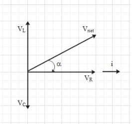
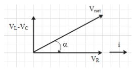
Hence, ${{V}_{net}}=\sqrt{V_{R}^{2}+{{\left( {{V}_{L}}-{{V}_{c}} \right)}^{2}}}$.
Angle $\alpha $ is the phase difference between the emf of the source (i.e. ${{V}_{net}}$) and current in the circuit.
Here, ${{V}_{R}}=iR$, where is the resistance.
${{V}_{L}}=i{{X}_{L}}$, where ${{X}_{L}}$ is inductive reactance. And ${{X}_{L}}=\omega L$, $\omega $ is the angular frequency of the source and L is the inductance.
$\Rightarrow {{V}_{L}}=i\omega L$
${{V}_{C}}=i{{X}_{C}}$, where ${{X}_{C}}$ is capacitive reactance. And ${{X}_{C}}=\dfrac{1}{\omega C}$, C is the capacitance.
$\Rightarrow {{V}_{C}}=\dfrac{i}{\omega C}$
From the figure we can make out that if ${{V}_{L}}$ > ${{V}_{C}}$, then ${{V}_{net}}$ will be in the first quadrant and phase angle $\alpha $will be positive. This means that the current lags the voltage.
Now, ${{V}_{L}}$ > ${{V}_{C}}$ $\Rightarrow i{{X}_{L}}$ > $i{{X}_{C}}$
$\Rightarrow {{X}_{L}}$ > ${{X}_{C}}$
Therefore, if ${{X}_{L}}$ > ${{X}_{C}}$, the current lags the voltage.
If ${{V}_{L}}$ < ${{V}_{C}}$, then ${{V}_{net}}$ will be in the fourth quadrant and phase angle $\alpha $will be negative. This means that the current leads the voltage.
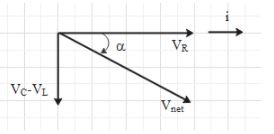
Therefore, if ${{X}_{L}}$ < ${{X}_{C}}$, the current leads the voltage.
Let us check the relation between ${{X}_{L}}$ and ${{X}_{C}}$ for the given circuit.
It is given that the capacitance C=30mF, inductance L=100mF and frequency f=50Hz.
Let use the formula $\omega =2\pi f$ to find angular frequency $\omega $.
Therefore, $\omega =2\pi (50)=100\pi {{s}^{-1}}$.
Let us calculate ${{X}_{L}}$ and ${{X}_{C}}$.
${{X}_{L}}=\omega L=100\pi \times 100\times {{10}^{-3}}=10\pi \Omega $
${{X}_{C}}=\dfrac{1}{\omega C}=\dfrac{1}{100\pi \times 30\times {{10}^{-3}}}=\dfrac{1}{3\pi }\Omega $
Therefore, ${{X}_{L}}$ > ${{X}_{C}}$.
This means that current lags the voltage.
Let them find the phase difference i.e. $\alpha $.
For this look at the second figure. Here, $\tan \alpha =\dfrac{{{V}_{L}}-{{V}_{C}}}{{{V}_{R}}}$
$\Rightarrow \tan \alpha =\dfrac{i{{X}_{L}}-i{{X}_{C}}}{iR}$
$\Rightarrow \tan \alpha =\dfrac{{{X}_{L}}-{{X}_{C}}}{R}$
Substitute the values of ${{X}_{L}}$, ${{X}_{C}}$ and R in the above equation.
$\Rightarrow \tan \alpha =\dfrac{10\pi -\dfrac{1}{3\pi }}{200}=0.15$
$\Rightarrow \alpha ={{\tan }^{-1}}0.15$
Note: Let us understand what it means when we say that the current is leading the source voltage or the current is lagging the source voltage.
When the current is leading the voltage, the current will reach its maximum value before the voltage reaches its maximum value.
When the current is lagging the voltage, the voltage will reach its maximum value before the current reaches its maximum value.
Formula used:
${{X}_{L}}=\omega L$
${{X}_{C}}=\dfrac{1}{\omega C}$
$\tan \alpha =\dfrac{{{V}_{L}}-{{V}_{C}}}{{{V}_{R}}}$
Complete step-by-step answer:
In an AC circuit, the voltage (potential difference) across the components in the circuit and the current flowing in the circuit are treated as vectors. The phase difference between the current and the voltage across the respective component is the angle between the current vector and the voltage vector of the component.
Since the voltage across the resistance and the current are always in phase, the vectors of voltage of resistance (${{V}_{R}}$) and current (i) are parallel.
There is a phase difference of $+\dfrac{\pi }{2}$ between the inductor voltage and the current. That is the inductor voltage leads the current by a phase of $\dfrac{\pi }{2}$.
Therefore, the vector of inductor voltage (${{V}_{L}}$) is at an angle of $+\dfrac{\pi }{2}$ from the current vector.
There is a phase difference of $-\dfrac{\pi }{2}$ between the capacitor voltage and the current. That is the capacitor voltage lags behind the current by a phase of $\dfrac{\pi }{2}$.
Therefore, the vector of capacitor voltage (${{V}_{c}}$) is at an angle of $-\dfrac{\pi }{2}$ from the current vector.
The entire can be summarised with the help of the diagram given below.
Hence, ${{V}_{net}}=\sqrt{V_{R}^{2}+{{\left( {{V}_{L}}-{{V}_{c}} \right)}^{2}}}$.
Angle $\alpha $ is the phase difference between the emf of the source (i.e. ${{V}_{net}}$) and current in the circuit.
Here, ${{V}_{R}}=iR$, where is the resistance.
${{V}_{L}}=i{{X}_{L}}$, where ${{X}_{L}}$ is inductive reactance. And ${{X}_{L}}=\omega L$, $\omega $ is the angular frequency of the source and L is the inductance.
$\Rightarrow {{V}_{L}}=i\omega L$
${{V}_{C}}=i{{X}_{C}}$, where ${{X}_{C}}$ is capacitive reactance. And ${{X}_{C}}=\dfrac{1}{\omega C}$, C is the capacitance.
$\Rightarrow {{V}_{C}}=\dfrac{i}{\omega C}$
From the figure we can make out that if ${{V}_{L}}$ > ${{V}_{C}}$, then ${{V}_{net}}$ will be in the first quadrant and phase angle $\alpha $will be positive. This means that the current lags the voltage.
Now, ${{V}_{L}}$ > ${{V}_{C}}$ $\Rightarrow i{{X}_{L}}$ > $i{{X}_{C}}$
$\Rightarrow {{X}_{L}}$ > ${{X}_{C}}$
Therefore, if ${{X}_{L}}$ > ${{X}_{C}}$, the current lags the voltage.
If ${{V}_{L}}$ < ${{V}_{C}}$, then ${{V}_{net}}$ will be in the fourth quadrant and phase angle $\alpha $will be negative. This means that the current leads the voltage.
Therefore, if ${{X}_{L}}$ < ${{X}_{C}}$, the current leads the voltage.
Let us check the relation between ${{X}_{L}}$ and ${{X}_{C}}$ for the given circuit.
It is given that the capacitance C=30mF, inductance L=100mF and frequency f=50Hz.
Let use the formula $\omega =2\pi f$ to find angular frequency $\omega $.
Therefore, $\omega =2\pi (50)=100\pi {{s}^{-1}}$.
Let us calculate ${{X}_{L}}$ and ${{X}_{C}}$.
${{X}_{L}}=\omega L=100\pi \times 100\times {{10}^{-3}}=10\pi \Omega $
${{X}_{C}}=\dfrac{1}{\omega C}=\dfrac{1}{100\pi \times 30\times {{10}^{-3}}}=\dfrac{1}{3\pi }\Omega $
Therefore, ${{X}_{L}}$ > ${{X}_{C}}$.
This means that current lags the voltage.
Let them find the phase difference i.e. $\alpha $.
For this look at the second figure. Here, $\tan \alpha =\dfrac{{{V}_{L}}-{{V}_{C}}}{{{V}_{R}}}$
$\Rightarrow \tan \alpha =\dfrac{i{{X}_{L}}-i{{X}_{C}}}{iR}$
$\Rightarrow \tan \alpha =\dfrac{{{X}_{L}}-{{X}_{C}}}{R}$
Substitute the values of ${{X}_{L}}$, ${{X}_{C}}$ and R in the above equation.
$\Rightarrow \tan \alpha =\dfrac{10\pi -\dfrac{1}{3\pi }}{200}=0.15$
$\Rightarrow \alpha ={{\tan }^{-1}}0.15$
Note: Let us understand what it means when we say that the current is leading the source voltage or the current is lagging the source voltage.
When the current is leading the voltage, the current will reach its maximum value before the voltage reaches its maximum value.
When the current is lagging the voltage, the voltage will reach its maximum value before the current reaches its maximum value.
Recently Updated Pages
Master Class 12 Economics: Engaging Questions & Answers for Success
Master Class 12 Physics: Engaging Questions & Answers for Success
Master Class 12 English: Engaging Questions & Answers for Success
Master Class 12 Social Science: Engaging Questions & Answers for Success
Master Class 12 Maths: Engaging Questions & Answers for Success
Master Class 12 Business Studies: Engaging Questions & Answers for Success
Trending doubts
Which are the Top 10 Largest Countries of the World?
What are the major means of transport Explain each class 12 social science CBSE
Draw a labelled sketch of the human eye class 12 physics CBSE
Why cannot DNA pass through cell membranes class 12 biology CBSE
Differentiate between insitu conservation and exsitu class 12 biology CBSE
Draw a neat and well labeled diagram of TS of ovary class 12 biology CBSE