


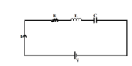
A sinusoidal voltage of peak value $283V$ and angular frequency $320{{s}^{-1}}$ is applied to a series LCR circuit. Given that $R=5\Omega, \text{ }L=25mH$ and $C=1000\mu F$. The total impedance and the phase difference between the voltage across the source and the current will respectively be:
$\begin{align}
& \text{A}\text{. }7\Omega \text{ and 4}{{\text{5}}^{\circ }} \\
& \text{B}\text{. }10\Omega \text{ and }{{\tan }^{-1}}\left( \dfrac{5}{3} \right) \\
& \text{C}\text{. }10\Omega \text{ and }{{\tan }^{-1}}\left( \dfrac{8}{3} \right) \\
& \text{D}\text{. }7\Omega \text{ and }{{\tan }^{-1}}\left( \dfrac{5}{3} \right) \\
\end{align}$
Answer
594.9k+ views
Hint: In a series LCR circuit, the electrical components; resistor, inductor and capacitor are connected end to end in the circuit. Impedance of a LCR circuit includes resistance \[\left( R \right)\], inductive reactance $\left( {{X}_{L}} \right)$ and capacitive reactance $\left( {{X}_{C}} \right)$.
Formula used:
Inductive reactance, ${{X}_{L}}=\omega L$
Capacitive reactance, ${{X}_{C}}=\dfrac{1}{\omega C}$
Impedance of series LCR circuit, $Z=\sqrt{{{R}^{2}}+{{\left( {{X}_{L}}-\dfrac{1}{{{X}_{C}}} \right)}^{2}}}$
Complete step by step answer:
Series LCR circuit is a type of electrical circuit in which the three circuit elements; Resistor, Inductor, and Capacitor are connected in series in the circuit.
Electrical impedance is the total opposition that an electrical circuit presents to alternating current. Impedance of a circuit is measured in ohms.
Impedance of series LCR circuit is given by,
$Z=\sqrt{{{R}^{2}}+{{\left( {{X}_{L}}-\dfrac{1}{{{X}_{C}}} \right)}^{2}}}$
Where,
$R$is the resistance
${{X}_{L}}$ is the inductive reactance
${{X}_{C}}$ is the capacitive reactance
If $V$ is the potential difference and $I$ is the current and $\phi $ is the phase difference, then,
$\tan \phi =\dfrac{{{X}_{L}}-{{X}_{C}}}{R}$
We are given a sinusoidal voltage of peak value $283V$and angular frequency $320{{s}^{-1}}$. Also, $R=5\Omega ,\text{ }L=25mH$ and $C=1000\mu F$.
Capacitive reactance is given as,
${{X}_{C}}=\dfrac{1}{\omega C}$
Putting values,
$\begin{align}
& \omega =320{{s}^{-1}} \\
& C=1000\mu F \\
\end{align}$
We get,
$\begin{align}
& {{X}_{C}}=\dfrac{1}{320\times 1000\times {{10}^{-6}}}=\dfrac{1}{320\times {{10}^{-3}}} \\
& {{X}_{C}}=3.125\Omega \\
\end{align}$
Inductive reactance is given as,
${{X}_{L}}=\omega L$
Putting values,
$\begin{align}
& \omega =320{{s}^{-1}} \\
& L=25mH \\
\end{align}$
We get,
$\begin{align}
& {{X}_{L}}=320\times 25\times {{10}^{-3}}=7000\times {{10}^{-3}} \\
& {{X}_{L}}=7\Omega \\
\end{align}$
Resistance is given as,
$R=5\Omega $
Expression for Impedance of a LCR circuit:
$Z=\sqrt{{{R}^{2}}+{{\left( {{X}_{L}}-\dfrac{1}{{{X}_{C}}} \right)}^{2}}}$
Where,
$R$ is the value of resistance
${{X}_{L}}$ is the Inductive reactance
${{X}_{C}}$ is the Capacitive reactance
We have,
$\begin{align}
& R=5\Omega \\
& {{X}_{L}}=7\Omega \\
& {{X}_{C}}=3.125\Omega \\
\end{align}$
$\begin{align}
&Z=\sqrt{{{\left( 5 \right)}^{2}}+{{\left( 8-3.125 \right)}^{2}}}=\sqrt{{{\left(5 \right)}^{2}}+{{\left( 4.875 \right)}^{2}}} \\
& Z=\sqrt{25+23.765}=\sqrt{48.765}\simeq 7 \\
& Z=7\Omega \\
\end{align}$
Now,
$\tan \phi =\dfrac{{{X}_{L}}-{{X}_{C}}}{R}$
Putting values,
$\begin{align}
& R=5\Omega \\
& {{X}_{L}}=7\Omega \\
& {{X}_{C}}=3.125\Omega \\
\end{align}$
$\begin{align}
& \tan \phi =\dfrac{8-3.125}{5}=\dfrac{4.875}{5}\approx 1 \\
& \phi ={{\tan }^{-1}}\left( 1 \right) \\
& \phi =\dfrac{\pi }{4} \\
\end{align}$
The total impedance of the circuit is $7\Omega $
The phase difference between the voltage across the source and the current is ${{45}^{\circ }}$
Hence, the correct option is A.
Note:
Series LCR circuit means that the three elements: Resistor, Inductor and Capacitor are connected end to end in a circuit. All the three elements individually offer some opposition to the flow of alternating current through the circuit. Impedance is the total opposition offered by these elements to the AC current in the circuit. The unit of Impedance is ohms. Impedance can be assumed as the analogue of resistance in an AC circuit.
Recently Updated Pages
Master Class 12 Economics: Engaging Questions & Answers for Success
Master Class 12 Physics: Engaging Questions & Answers for Success
Master Class 12 English: Engaging Questions & Answers for Success
Master Class 12 Social Science: Engaging Questions & Answers for Success
Master Class 12 Maths: Engaging Questions & Answers for Success
Master Class 12 Business Studies: Engaging Questions & Answers for Success
Trending doubts
Which are the Top 10 Largest Countries of the World?
What are the major means of transport Explain each class 12 social science CBSE
Draw a labelled sketch of the human eye class 12 physics CBSE
Why cannot DNA pass through cell membranes class 12 biology CBSE
Differentiate between insitu conservation and exsitu class 12 biology CBSE
Draw a neat and well labeled diagram of TS of ovary class 12 biology CBSE