


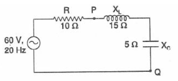
A series RLC circuit is made as shown in the figure with an AC source of 60 V, 20 Hz. Then
This question has multiple correct options
A. The rms current through the resistor R is 4.2 A
B. The effective potential difference between P and Q should be 42 V.
C. The instantaneous current leads the source voltage by $45{}^\circ $
D. The instantaneous current lags behind the applied voltage by $45{}^\circ $
Answer
598.8k+ views
Hint: First calculate the impedance of the circuit . Then calculate the rms current through the resistor which is given by the ratio of rms voltage and the impedance. After that calculate the potential difference between the points P and Q. See the phase difference between the instantaneous current and source. Then compare all the results to see which option is correct.
Formulas used:
The impedance of the circuit is given by
$Z=\sqrt{{{R}^{2}}+{{\left( {{X}_{L}}-{{X}_{C}} \right)}^{2}}}$
Where $R$ the resistance of the circuit, ${{X}_{L}}$ is the inductive reactance and ${{X}_{C}}$ is the capacitive reactance.
${{I}_{rms}}=\dfrac{{{V}_{\max }}}{Z}$
$\tan \phi =\dfrac{{{X}_{L}}-{{X}_{C}}}{R}$
Where $\phi$ is the angle between current and voltage. Or phase difference
Complete answer:
Given the emf of the ac source is of \[60V\] and the frequency is \[20Hz\].
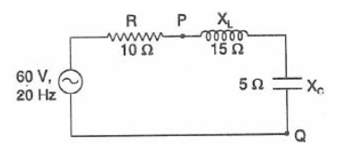
So ${{V}_{\max }}=60V$ and frequency,$f=20Hz$
So the angular frequency
$\omega =2\pi f=40\pi $
Now
$Z=\sqrt{{{R}^{2}}+{{\left( {{X}_{L}}-{{X}_{C}} \right)}^{2}}}=\sqrt{100+{{\left( 15-5 \right)}^{2}}}=\sqrt{200}=10\sqrt{2}\ \Omega $
Now the root mean square current is given by
\[{{I}_{rms}}=\dfrac{{{V}_{\max }}}{Z}=\dfrac{60}{10\sqrt{2}}=\dfrac{6}{\sqrt{2}}=3\sqrt{2}=3\times 1.141=4.2A\]
So the option A is correct.
The equivalent reactance between the point P and Q is
$R'={{X}_{L}}-{{X}_{C}}=15-5=10\Omega $
So the potential difference between the points P and Q is
$V=IR'=4.2\times 10=42V$
So the option B is also correct.
The phase difference between the current and voltage is given by
$\phi ={{\tan }^{-1}}\dfrac{{{X}_{L}}-{{X}_{C}}}{R}={{\tan }^{-1}}\dfrac{15-5}{10}={{\tan }^{-1}}\left( 1 \right)=45{}^\circ $
As ${{X}_{L}}>{{X}_{C}}$ so the circuit will be more inductive than capacitive and the source voltage will lead the current by an angle $45{}^\circ $
Or the instantaneous current lags behind the applied voltage by $45{}^\circ $.
So the option D is also correct.
So the correct options are A,B and D.
Note:
For a RLC circuit if ${{X}_{L}}>{{X}_{C}}$ then current will be more inductive than capacitive and the phase will be positive for this circuit. So the current will lag behind the applied voltage.
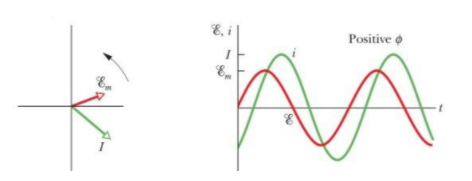
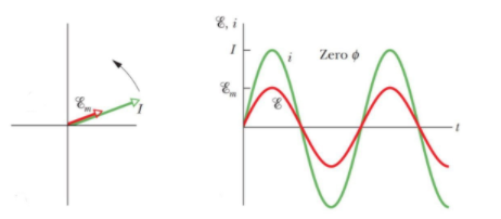
In the figure ${{\mathcal{E}}_{m}}$ = max emf of the applied source.
If ${{X}_{C}}>{{X}_{L}}$ then the circuit is said to be more capacitive than inductive. So the phase $\tan \phi $ is negative and that means the applied emf will lag behind the current. i.e.
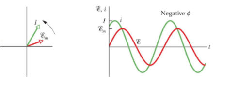
In the figure ${{\mathcal{E}}_{m}}=\text{ max emf of the applied source}$.
If ${{X}_{C}}={{X}_{L}}$ which is the resonant condition the circuit will resist and in the resistive circuit the current and supplied emf is in the same phase.
In the figure ${{\mathcal{E}}_{m}}=\text{ max emf of the applied source}$.
Formulas used:
The impedance of the circuit is given by
$Z=\sqrt{{{R}^{2}}+{{\left( {{X}_{L}}-{{X}_{C}} \right)}^{2}}}$
Where $R$ the resistance of the circuit, ${{X}_{L}}$ is the inductive reactance and ${{X}_{C}}$ is the capacitive reactance.
${{I}_{rms}}=\dfrac{{{V}_{\max }}}{Z}$
$\tan \phi =\dfrac{{{X}_{L}}-{{X}_{C}}}{R}$
Where $\phi$ is the angle between current and voltage. Or phase difference
Complete answer:
Given the emf of the ac source is of \[60V\] and the frequency is \[20Hz\].
So ${{V}_{\max }}=60V$ and frequency,$f=20Hz$
So the angular frequency
$\omega =2\pi f=40\pi $
Now
$Z=\sqrt{{{R}^{2}}+{{\left( {{X}_{L}}-{{X}_{C}} \right)}^{2}}}=\sqrt{100+{{\left( 15-5 \right)}^{2}}}=\sqrt{200}=10\sqrt{2}\ \Omega $
Now the root mean square current is given by
\[{{I}_{rms}}=\dfrac{{{V}_{\max }}}{Z}=\dfrac{60}{10\sqrt{2}}=\dfrac{6}{\sqrt{2}}=3\sqrt{2}=3\times 1.141=4.2A\]
So the option A is correct.
The equivalent reactance between the point P and Q is
$R'={{X}_{L}}-{{X}_{C}}=15-5=10\Omega $
So the potential difference between the points P and Q is
$V=IR'=4.2\times 10=42V$
So the option B is also correct.
The phase difference between the current and voltage is given by
$\phi ={{\tan }^{-1}}\dfrac{{{X}_{L}}-{{X}_{C}}}{R}={{\tan }^{-1}}\dfrac{15-5}{10}={{\tan }^{-1}}\left( 1 \right)=45{}^\circ $
As ${{X}_{L}}>{{X}_{C}}$ so the circuit will be more inductive than capacitive and the source voltage will lead the current by an angle $45{}^\circ $
Or the instantaneous current lags behind the applied voltage by $45{}^\circ $.
So the option D is also correct.
So the correct options are A,B and D.
Note:
For a RLC circuit if ${{X}_{L}}>{{X}_{C}}$ then current will be more inductive than capacitive and the phase will be positive for this circuit. So the current will lag behind the applied voltage.
In the figure ${{\mathcal{E}}_{m}}$ = max emf of the applied source.
If ${{X}_{C}}>{{X}_{L}}$ then the circuit is said to be more capacitive than inductive. So the phase $\tan \phi $ is negative and that means the applied emf will lag behind the current. i.e.
In the figure ${{\mathcal{E}}_{m}}=\text{ max emf of the applied source}$.
If ${{X}_{C}}={{X}_{L}}$ which is the resonant condition the circuit will resist and in the resistive circuit the current and supplied emf is in the same phase.
In the figure ${{\mathcal{E}}_{m}}=\text{ max emf of the applied source}$.
Recently Updated Pages
Basicity of sulphurous acid and sulphuric acid are
Master Class 12 English: Engaging Questions & Answers for Success
Master Class 12 Social Science: Engaging Questions & Answers for Success
Master Class 12 Maths: Engaging Questions & Answers for Success
Master Class 12 Economics: Engaging Questions & Answers for Success
Master Class 12 Physics: Engaging Questions & Answers for Success
Trending doubts
Which are the Top 10 Largest Countries of the World?
Draw a labelled sketch of the human eye class 12 physics CBSE
Which state in the country is at the forefront in controlling class 12 social science CBSE
Where is the largest hydroelectric power station located class 12 biology CBSE
Which country did Danny Casey play for class 12 english CBSE
Coming together federation is practiced in A India class 12 social science CBSE