


When a resistor R is connected in series with an element A, the electric current is found to be lagging behind the voltage by angle \[{{\theta }_{1}}\]. When the same resistance is connected in series with element B, current leads voltage by \[{{\theta }_{2}}\]. When R, A, B are connected in series, the current now leads voltage by theta. Assume the same AC source is used in all cases then:
\[A.\,\theta ={{\theta }_{2}}-{{\theta }_{1}}\]
\[B.\,\tan \theta =\tan {{\theta }_{2}}-\tan {{\theta }_{1}}\]
\[C.\, \theta =\dfrac {{{\theta }_{1}}- {{\theta }_{2}}} {2}\]
D. None of these
Answer
602.7k+ views
Hint: The lagging and leading conditions of the electric current and the voltage in the given are used to find the elements present in the circuit, that is, we will first find the type of elements A and B are. Then, we will substitute the values of the ratios obtained in first and second cases in the third case, as per the given cases.
Formula used: \[\tan \theta =\dfrac{{{X}_{L}}}{R}\]
\[\tan \theta =\dfrac{{{X}_{C}}}{R}\]
Complete step by step answer:
There are a total of 3 cases that can be considered based on the data given to us.
They are discussed as follows.
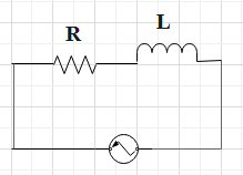
Case I : A – R circuit
In this case, a resistance R is connected in series with an element A. For this arrangement, the electric current is found to be lagging behind the voltage by an angle of the value of \[{{\theta }_{1}}\].
Thus, the result of this arrangement is that the voltage leads. And, this type of result is only possible, when there is an inductor connected in the circuit.
Thus, the element A is considered to be an inductor.
The circuit diagram of RL.
The phasor diagram of series RL circuit
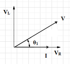
Thus, the ratio can be found to be equal to the value of, \[\tan {{\theta }_{1}}=\dfrac{{{X}_{L}}}{R}\]
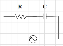
Case II : B – R circuit
In this case, a resistance R is connected in series with an element B. For this arrangement, the voltage is found to be lagging behind the electric current by an angle of the value of \[{{\theta }_{2}}\].
Thus, the result of this arrangement is that the electric current leads. And, this type of result is only possible, when there is a capacitor connected in the circuit.
Thus, the element B is considered to be a capacitor.
The circuit diagram of RC.
The phasor diagram of the series RC circuit
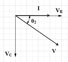
Thus, the ratio can be found to be equal to the value of, \[\tan {{\theta }_{2}}=\dfrac{{{X}_{C}}}{R}\]
Case III : A – R – B circuit
In this case, a resistance R is connected in series with an element B and an element A. For this arrangement, the electric current is found to be lagging behind the voltage by an angle of the value of \[\theta \].
As we have already determined the type of elements A and B are. So, the circuit consists of a resistor R, a capacitor B and an inductor A.
The circuit diagram of RLC.

Thus, the result of this arrangement is that the electric current leads. And, this type of result is only possible, when the value of the capacitive reactance is more than that of the inductive reactance.
The phasor diagram of series RLC circuit
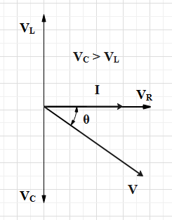
Thus, the ratio can be found to be equal to the value of, \[\tan \theta =\dfrac{{{X}_{C}}-{{X}_{L}}}{R}\].
Substitute the values of the angles of the tan function obtained in the above-discussed cases.
So, we have,
\[\begin{align}
& \tan \theta =\dfrac{{{X}_{C}}}{R}-\dfrac{{{X}_{L}}}{R} \\
& \Rightarrow \tan \theta =\tan {{\theta }_{2}}-\tan {{\theta }_{1}} \\
\end{align}\]
As the value results to\[\tan \theta =\tan {{\theta }_{2}}-\tan {{\theta }_{1}}\]
So, the correct answer is “Option B”.
Note: The important points to be remembered are: The circuit in which the electric current lags behind the voltage will be a circuit consisting of the inductor and a resistor. The circuit in which the voltage lags behind the electric current will be a circuit consisting of a capacitor and a resistor.
Formula used: \[\tan \theta =\dfrac{{{X}_{L}}}{R}\]
\[\tan \theta =\dfrac{{{X}_{C}}}{R}\]
Complete step by step answer:
There are a total of 3 cases that can be considered based on the data given to us.
They are discussed as follows.
Case I : A – R circuit
In this case, a resistance R is connected in series with an element A. For this arrangement, the electric current is found to be lagging behind the voltage by an angle of the value of \[{{\theta }_{1}}\].
Thus, the result of this arrangement is that the voltage leads. And, this type of result is only possible, when there is an inductor connected in the circuit.
Thus, the element A is considered to be an inductor.
The circuit diagram of RL.
The phasor diagram of series RL circuit
Thus, the ratio can be found to be equal to the value of, \[\tan {{\theta }_{1}}=\dfrac{{{X}_{L}}}{R}\]
Case II : B – R circuit
In this case, a resistance R is connected in series with an element B. For this arrangement, the voltage is found to be lagging behind the electric current by an angle of the value of \[{{\theta }_{2}}\].
Thus, the result of this arrangement is that the electric current leads. And, this type of result is only possible, when there is a capacitor connected in the circuit.
Thus, the element B is considered to be a capacitor.
The circuit diagram of RC.
The phasor diagram of the series RC circuit
Thus, the ratio can be found to be equal to the value of, \[\tan {{\theta }_{2}}=\dfrac{{{X}_{C}}}{R}\]
Case III : A – R – B circuit
In this case, a resistance R is connected in series with an element B and an element A. For this arrangement, the electric current is found to be lagging behind the voltage by an angle of the value of \[\theta \].
As we have already determined the type of elements A and B are. So, the circuit consists of a resistor R, a capacitor B and an inductor A.
The circuit diagram of RLC.
Thus, the result of this arrangement is that the electric current leads. And, this type of result is only possible, when the value of the capacitive reactance is more than that of the inductive reactance.
The phasor diagram of series RLC circuit
Thus, the ratio can be found to be equal to the value of, \[\tan \theta =\dfrac{{{X}_{C}}-{{X}_{L}}}{R}\].
Substitute the values of the angles of the tan function obtained in the above-discussed cases.
So, we have,
\[\begin{align}
& \tan \theta =\dfrac{{{X}_{C}}}{R}-\dfrac{{{X}_{L}}}{R} \\
& \Rightarrow \tan \theta =\tan {{\theta }_{2}}-\tan {{\theta }_{1}} \\
\end{align}\]
As the value results to\[\tan \theta =\tan {{\theta }_{2}}-\tan {{\theta }_{1}}\]
So, the correct answer is “Option B”.
Note: The important points to be remembered are: The circuit in which the electric current lags behind the voltage will be a circuit consisting of the inductor and a resistor. The circuit in which the voltage lags behind the electric current will be a circuit consisting of a capacitor and a resistor.
Recently Updated Pages
Three beakers labelled as A B and C each containing 25 mL of water were taken A small amount of NaOH anhydrous CuSO4 and NaCl were added to the beakers A B and C respectively It was observed that there was an increase in the temperature of the solutions contained in beakers A and B whereas in case of beaker C the temperature of the solution falls Which one of the following statements isarecorrect i In beakers A and B exothermic process has occurred ii In beakers A and B endothermic process has occurred iii In beaker C exothermic process has occurred iv In beaker C endothermic process has occurred
Master Class 12 Social Science: Engaging Questions & Answers for Success
Master Class 12 Physics: Engaging Questions & Answers for Success
Master Class 12 Maths: Engaging Questions & Answers for Success
Master Class 12 Economics: Engaging Questions & Answers for Success
Master Class 12 Chemistry: Engaging Questions & Answers for Success
Three beakers labelled as A B and C each containing 25 mL of water were taken A small amount of NaOH anhydrous CuSO4 and NaCl were added to the beakers A B and C respectively It was observed that there was an increase in the temperature of the solutions contained in beakers A and B whereas in case of beaker C the temperature of the solution falls Which one of the following statements isarecorrect i In beakers A and B exothermic process has occurred ii In beakers A and B endothermic process has occurred iii In beaker C exothermic process has occurred iv In beaker C endothermic process has occurred
Master Class 12 Social Science: Engaging Questions & Answers for Success
Master Class 12 Physics: Engaging Questions & Answers for Success
Trending doubts
Which are the Top 10 Largest Countries of the World?
Draw a labelled sketch of the human eye class 12 physics CBSE
Differentiate between homogeneous and heterogeneous class 12 chemistry CBSE
What are the major means of transport Explain each class 12 social science CBSE
Sulphuric acid is known as the king of acids State class 12 chemistry CBSE
Why should a magnesium ribbon be cleaned before burning class 12 chemistry CBSE