


A resistance and inductance are connected in series with a source of alternating e.m.f. Derive an expression for resultant voltage impedance and phase difference between current and voltage in alternating circuits.
Answer
612.9k+ views
Hint: We know that voltage across the inductance \[{V_L}({V_L} = I{X_L})\] is leading voltage across the resistance \[{V_R}({V_R} = IR)\] with a phase difference of ${90^ \circ }$. We have to find the resultant of \[{V_L}\] and \[{V_R}\] to find the impedance voltage of the circuit. The relation between \[{V_L}\] and \[{V_R}\] gives the phase difference.
Complete step by step answer:
According to the question, the resistance \[R\] and the inductance \[L\] are connected in the series to an AC source which is shown in the below figure.
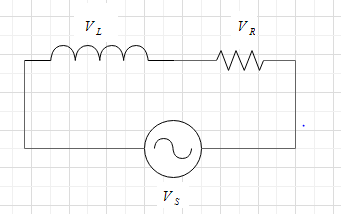
At any instance the a.c. voltage is given by-
$V = {V_0}\sin \omega t$
let \[I\] be the current which flows through the circuit.
So,
Phase difference across \[R\] will be given as ${V_R} = IR$
Phase difference across \[L\] will be given as ${V_L} = I{X_L}$
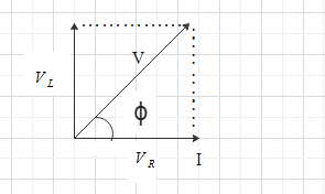
Here, we know that the \[{V_R}\] and \[I\] are in the same phase but \[{V_L}\] is leading and has a phase difference of ${90^ \circ }$.
In this way, the angle between \[{V_L}\] and \[{V_R}\] is equal to ${90^ \circ }$.
Let us find the resultant of \[{V_R}\] and \[{V_L}\] which is given by \[V\].
$
{V^2} = {V_R}^2 + {V_L}^2 \\
\Rightarrow V2 = {(IR)^2} + {(I{X_L})^2} \\
$
$
\Rightarrow {V^2} = {I^2}({R^2} + {X_L}^2) \\
\Rightarrow \dfrac{{{V^2}}}{{{I^2}}} = ({R^2} + {X_L}^2) \\
$
We have $\dfrac{V}{I} = Z$ where $Z$ is known as impedance.
So, the equation becomes-
${Z^2} = {R^2} + {X_L}^2$
or the equation can be written as $Z = \sqrt {{R^2} + {X_L}^2} $
Now, we have ${X_L} = L\omega $. Putting this value in the above equation, we get-
$Z = \sqrt {{R^2} + {L^2}{\omega ^2}} $
We know that the resultant $V$ is leading then current \[I\] flows in circuit. So,
${I_0} = \dfrac{{{V_0}}}{Z}$
or the equation will becomes,
${I_0} = \dfrac{{{V_{^0}}}}{{\sqrt {{R^2} + {L^2}{\omega ^2}} }}$
let the phase difference between \[V\] and \[I\] is $\phi $, then we have-
$\tan \phi = \dfrac{{{V_L}}}{{{V_R}}}$
Putting the values of \[{V_L}\] and \[{V_R}\] in the above equation. We get-
$\tan \phi = \dfrac{{I{X_L}}}{{IR}} = \dfrac{{{X_L}}}{R}$
So, the phase difference will be-
$\phi = {\tan ^{ - 1}}\dfrac{{{X_L}}}{R}$
So, the resultant impedance voltage is $Z = \sqrt {{R^2} + {L^2}{\omega ^2}} $and the phase difference between current and voltage is $\phi = {\tan ^{ - 1}}\dfrac{{{X_L}}}{R}$.
Note:
In a series circuit, the input current is equal to the output current while in the parallel circuit, the input voltage is equal to the output voltage. So, in the series circuit, we have to calculate the resultant voltage to find the impedance while in a parallel circuit, we have to calculate the resultant current to find the impedance. In a series circuit, the resultant voltage is a real number while in a parallel circuit the resultant current is either a real number or an imaginary number. In the series circuit, the resultant will be found in the first quadrant while in the parallel circuit, the resultant will be found in the fourth quadrant.
Complete step by step answer:
According to the question, the resistance \[R\] and the inductance \[L\] are connected in the series to an AC source which is shown in the below figure.
At any instance the a.c. voltage is given by-
$V = {V_0}\sin \omega t$
let \[I\] be the current which flows through the circuit.
So,
Phase difference across \[R\] will be given as ${V_R} = IR$
Phase difference across \[L\] will be given as ${V_L} = I{X_L}$
Here, we know that the \[{V_R}\] and \[I\] are in the same phase but \[{V_L}\] is leading and has a phase difference of ${90^ \circ }$.
In this way, the angle between \[{V_L}\] and \[{V_R}\] is equal to ${90^ \circ }$.
Let us find the resultant of \[{V_R}\] and \[{V_L}\] which is given by \[V\].
$
{V^2} = {V_R}^2 + {V_L}^2 \\
\Rightarrow V2 = {(IR)^2} + {(I{X_L})^2} \\
$
$
\Rightarrow {V^2} = {I^2}({R^2} + {X_L}^2) \\
\Rightarrow \dfrac{{{V^2}}}{{{I^2}}} = ({R^2} + {X_L}^2) \\
$
We have $\dfrac{V}{I} = Z$ where $Z$ is known as impedance.
So, the equation becomes-
${Z^2} = {R^2} + {X_L}^2$
or the equation can be written as $Z = \sqrt {{R^2} + {X_L}^2} $
Now, we have ${X_L} = L\omega $. Putting this value in the above equation, we get-
$Z = \sqrt {{R^2} + {L^2}{\omega ^2}} $
We know that the resultant $V$ is leading then current \[I\] flows in circuit. So,
${I_0} = \dfrac{{{V_0}}}{Z}$
or the equation will becomes,
${I_0} = \dfrac{{{V_{^0}}}}{{\sqrt {{R^2} + {L^2}{\omega ^2}} }}$
let the phase difference between \[V\] and \[I\] is $\phi $, then we have-
$\tan \phi = \dfrac{{{V_L}}}{{{V_R}}}$
Putting the values of \[{V_L}\] and \[{V_R}\] in the above equation. We get-
$\tan \phi = \dfrac{{I{X_L}}}{{IR}} = \dfrac{{{X_L}}}{R}$
So, the phase difference will be-
$\phi = {\tan ^{ - 1}}\dfrac{{{X_L}}}{R}$
So, the resultant impedance voltage is $Z = \sqrt {{R^2} + {L^2}{\omega ^2}} $and the phase difference between current and voltage is $\phi = {\tan ^{ - 1}}\dfrac{{{X_L}}}{R}$.
Note:
In a series circuit, the input current is equal to the output current while in the parallel circuit, the input voltage is equal to the output voltage. So, in the series circuit, we have to calculate the resultant voltage to find the impedance while in a parallel circuit, we have to calculate the resultant current to find the impedance. In a series circuit, the resultant voltage is a real number while in a parallel circuit the resultant current is either a real number or an imaginary number. In the series circuit, the resultant will be found in the first quadrant while in the parallel circuit, the resultant will be found in the fourth quadrant.
Recently Updated Pages
Master Class 12 Economics: Engaging Questions & Answers for Success
Master Class 12 English: Engaging Questions & Answers for Success
Master Class 12 Social Science: Engaging Questions & Answers for Success
Master Class 12 Maths: Engaging Questions & Answers for Success
Master Class 12 Physics: Engaging Questions & Answers for Success
Master Class 9 General Knowledge: Engaging Questions & Answers for Success
Trending doubts
Which are the Top 10 Largest Countries of the World?
Draw a labelled sketch of the human eye class 12 physics CBSE
Differentiate between homogeneous and heterogeneous class 12 chemistry CBSE
Why is the cell called the structural and functional class 12 biology CBSE
Draw ray diagrams each showing i myopic eye and ii class 12 physics CBSE
Which is the correct genotypic ratio of mendel dihybrid class 12 biology CBSE