


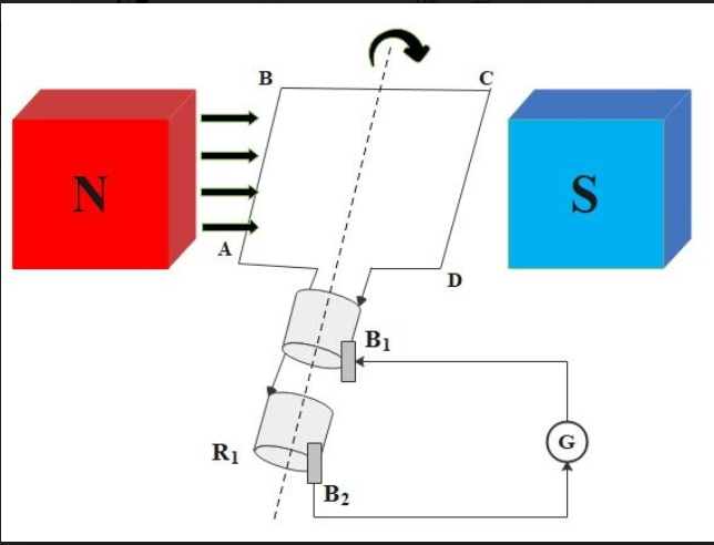
A. Redraw the diagram.
B. This diagram represents…..
C. Label the parts of the diagram.
D. Mention the principle used in devices denoted by this diagram.
Answer
620.7k+ views
Hint: AC generator works on Faraday's law of electromagnetic induction. It states that electromotive force is generated in a conductor while the current will change through that conductor. It requires a strong magnetic field that we can get by using a permanent magnet. As you can see in the diagram, the diagram consists of a coil, magnet, and galvanometer to measure the change in current. Because of a permanent magnet, a field will produce. This arrangement resembles Faraday's laws which are famous for generating an AC generator.
Complete step by step answer:
A. As shown in the diagram, diagrams are labeled.
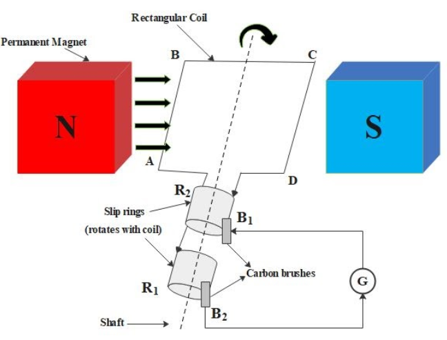
B. As you can see, the diagram represents an AC Generator.
C. The parts of the AC generator are labeled.
D. The working principle of the diagram is given below:
In an electric generator, mechanical energy is used to produce electricity by rotating the conductor in a magnetic field. This electric generator has a rotating rectangular coil ABCD which is placed between the two poles of a permanent magnet. The coil has two ends and these two ends are connected to the two rings R1 and R2. The inner side of a ring (R1 and R2) are made insulated. B1 and B2 are two conducting stationary brushes which are kept pressed separately on R1 and R2, respectively. R1and R2 are internally attached to an axle. Inside the magnetic field, the axle may be mechanically rotated from outside to rotate the coil. In a given external circuit, the outer end of the two brushes is connected to the galvanometer to show the flow of current. The axle which is attached to the two rings rotates such that AB moves up, at the same time CD moves down in the magnetic field which is produced by the Permanent magnet.
Let's say that Coil ABCD rotates clockwise in the diagram. Using the flaming right-hand rule, the induced current is set up in these arms along the direction AB and CD. Now the induced current will flow in the direction of ABCD. If the coil has a large number of turns, the current which is generated in turns of the coil adds up to give a huge current in the coil. This indicates that the current in the circuit must flow from B1 to B2. After half rotation, the CD arm will start moving up and AB starts moving down. AS a result, the direction of induced current will change in both AB and CD arms. This gives rise to the net induced current in the direction of DCBA. The current in the external circuit flows from B1 to B2 brushes. So after every half rotation, the polarity of the current in the respective AB and CD will change . Such a current is called alternating current because in this experiment, the current changes its direction at an equal interval of time. Hence alternating current is produced by the AC generator.
Note:
Note that the coil ABCD is rotating which is responsible for cutting the magnetic field. The electromotive generated in the conductor can be achieved by rotating a conduction coil or by rotating a magnetic field that contains a stationary conductor. The main components in an AC generator which you must know are field, coil, magnet, current, slip rings. An AC generator is used to generate electrical energy. Students should know that the AC generator can be stepped up transformers or stepped down transformers easily.
Complete step by step answer:
A. As shown in the diagram, diagrams are labeled.
B. As you can see, the diagram represents an AC Generator.
C. The parts of the AC generator are labeled.
D. The working principle of the diagram is given below:
In an electric generator, mechanical energy is used to produce electricity by rotating the conductor in a magnetic field. This electric generator has a rotating rectangular coil ABCD which is placed between the two poles of a permanent magnet. The coil has two ends and these two ends are connected to the two rings R1 and R2. The inner side of a ring (R1 and R2) are made insulated. B1 and B2 are two conducting stationary brushes which are kept pressed separately on R1 and R2, respectively. R1and R2 are internally attached to an axle. Inside the magnetic field, the axle may be mechanically rotated from outside to rotate the coil. In a given external circuit, the outer end of the two brushes is connected to the galvanometer to show the flow of current. The axle which is attached to the two rings rotates such that AB moves up, at the same time CD moves down in the magnetic field which is produced by the Permanent magnet.
Let's say that Coil ABCD rotates clockwise in the diagram. Using the flaming right-hand rule, the induced current is set up in these arms along the direction AB and CD. Now the induced current will flow in the direction of ABCD. If the coil has a large number of turns, the current which is generated in turns of the coil adds up to give a huge current in the coil. This indicates that the current in the circuit must flow from B1 to B2. After half rotation, the CD arm will start moving up and AB starts moving down. AS a result, the direction of induced current will change in both AB and CD arms. This gives rise to the net induced current in the direction of DCBA. The current in the external circuit flows from B1 to B2 brushes. So after every half rotation, the polarity of the current in the respective AB and CD will change . Such a current is called alternating current because in this experiment, the current changes its direction at an equal interval of time. Hence alternating current is produced by the AC generator.
Note:
Note that the coil ABCD is rotating which is responsible for cutting the magnetic field. The electromotive generated in the conductor can be achieved by rotating a conduction coil or by rotating a magnetic field that contains a stationary conductor. The main components in an AC generator which you must know are field, coil, magnet, current, slip rings. An AC generator is used to generate electrical energy. Students should know that the AC generator can be stepped up transformers or stepped down transformers easily.
Recently Updated Pages
Master Class 12 Business Studies: Engaging Questions & Answers for Success
Master Class 12 Biology: Engaging Questions & Answers for Success
Master Class 12 Chemistry: Engaging Questions & Answers for Success
Class 12 Question and Answer - Your Ultimate Solutions Guide
Master Class 11 Social Science: Engaging Questions & Answers for Success
Master Class 11 English: Engaging Questions & Answers for Success
Trending doubts
Which are the Top 10 Largest Countries of the World?
Draw a labelled sketch of the human eye class 12 physics CBSE
Differentiate between homogeneous and heterogeneous class 12 chemistry CBSE
Sulphuric acid is known as the king of acids State class 12 chemistry CBSE
Why is the cell called the structural and functional class 12 biology CBSE
Which is the correct genotypic ratio of mendel dihybrid class 12 biology CBSE