


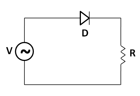
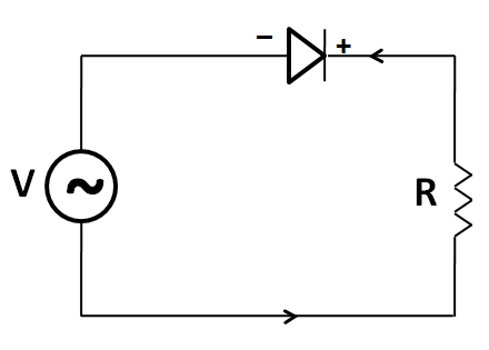
A p-n junction diode shown in the figure can act as a rectifier. An alternating current source $\left( V \right)$ is connected in the circuit. The current $\left( I \right)$ in the resistor $\left( R \right)$ can be shown by
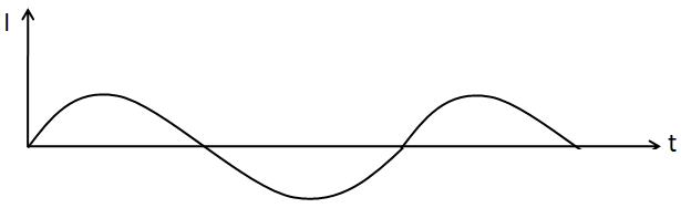
A)
B)
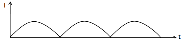
C)
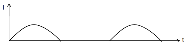
D)
Answer
574.5k+ views
Hint: To answer this question, we have to assume a particular input signal and divide the signal into two half cycles. Then we need to take the output for each half cycle to predict the output signal.
Complete step by step solution:
Let the input signal of the current source $\left( V \right)$ be shown as
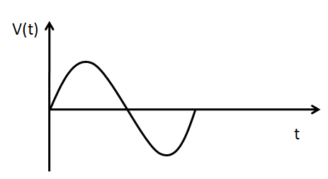
Now, we consider the two half cycles of the input signal separately.
Positive half cycle:
For the positive half cycle, let the direction of the input current in the circuit be clockwise. So the polarity of the voltage across the diode is as shown below.
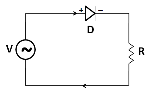
As we can see in the above circuit that the diode is forward biased. So we can replace it by a conducting wire as shown below.
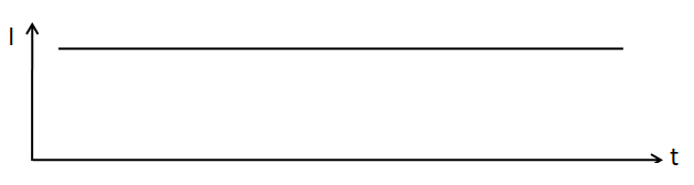
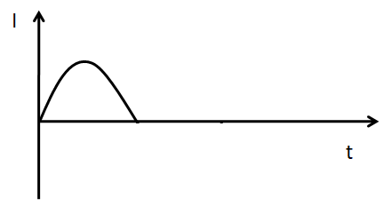
As there is no resistance in between the current source $\left( V \right)$ and the output resistor $\left( R \right)$, so the output current $\left( I \right)$ through the resistor is the same as the input signal. Therefore the output current signal is shown by
Negative half cycle:
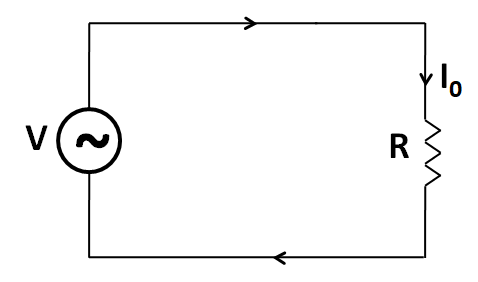
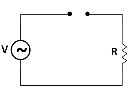
For the negative half cycle, the direction of the current will be reversed to the previous case. So the input current in the circuit will be in the anti-clockwise direction. Thus the polarity of the voltage across the diode can be shown as below.
Now, we can clearly see in the above circuit that the diode is reversed biased. So we can replace the diode by an open circuit as shown below.
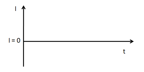
As the circuit is not complete, no current will flow through the resistor. So, the output current for this whole cycle is equal to zero, which can be shown as below.
Now, combining the output current signals for the two half cycles, we get the following shape of the output signal.
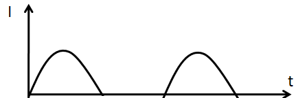
Hence the correct answer is option (C).
Note:
Although the waveform of the input signal is not given, we can assume it to be of any form. We do not have to worry about the shape, frequency or phase of the input signal. In this question, it is only required to predict the form of the output current. So for any continuous input current, the shape of output current can be predicted.
Complete step by step solution:
Let the input signal of the current source $\left( V \right)$ be shown as
Now, we consider the two half cycles of the input signal separately.
Positive half cycle:
For the positive half cycle, let the direction of the input current in the circuit be clockwise. So the polarity of the voltage across the diode is as shown below.
As we can see in the above circuit that the diode is forward biased. So we can replace it by a conducting wire as shown below.
As there is no resistance in between the current source $\left( V \right)$ and the output resistor $\left( R \right)$, so the output current $\left( I \right)$ through the resistor is the same as the input signal. Therefore the output current signal is shown by
Negative half cycle:
For the negative half cycle, the direction of the current will be reversed to the previous case. So the input current in the circuit will be in the anti-clockwise direction. Thus the polarity of the voltage across the diode can be shown as below.
Now, we can clearly see in the above circuit that the diode is reversed biased. So we can replace the diode by an open circuit as shown below.
As the circuit is not complete, no current will flow through the resistor. So, the output current for this whole cycle is equal to zero, which can be shown as below.
Now, combining the output current signals for the two half cycles, we get the following shape of the output signal.
Hence the correct answer is option (C).
Note:
Although the waveform of the input signal is not given, we can assume it to be of any form. We do not have to worry about the shape, frequency or phase of the input signal. In this question, it is only required to predict the form of the output current. So for any continuous input current, the shape of output current can be predicted.
Recently Updated Pages
Master Class 12 Economics: Engaging Questions & Answers for Success
Master Class 12 Physics: Engaging Questions & Answers for Success
Master Class 12 English: Engaging Questions & Answers for Success
Master Class 12 Social Science: Engaging Questions & Answers for Success
Master Class 12 Maths: Engaging Questions & Answers for Success
Master Class 12 Business Studies: Engaging Questions & Answers for Success
Trending doubts
Which are the Top 10 Largest Countries of the World?
What are the major means of transport Explain each class 12 social science CBSE
Draw a labelled sketch of the human eye class 12 physics CBSE
Why cannot DNA pass through cell membranes class 12 biology CBSE
Differentiate between insitu conservation and exsitu class 12 biology CBSE
Draw a neat and well labeled diagram of TS of ovary class 12 biology CBSE