


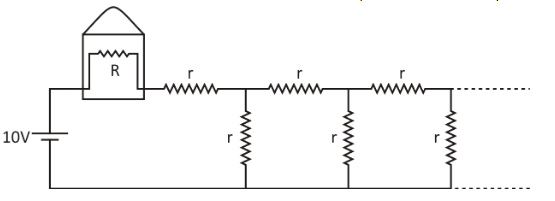
A light bulb of resistance \[R\] equals \[16\,\Omega \] is attached in series with an infinite resistor network with identical resistances \[r\] as shown below. A \[10\,{\text{V}}\] battery drives current in the circuit. What should be the value of \[r\] such that the bulb dissipated about \[1\,{\text{W}}\] of power?
A. \[14.8\,\Omega \]
B. \[29.6\,\Omega \]
C. \[7.4\,\Omega \]
D. \[3.7\,\Omega \]
Answer
607.8k+ views
Hint:First of all, we will find the external resistance, by using the expression of power. After that we will draw the circuit and try to reduce the infinite resistors, such that we can calculate the value of the identical resistors. Ohm’s law comes handy in this problem too.
Formula used:
We have Ohm’s law:
\[V = iR\] …… (1)
Where,
\[V\] indicates voltage.
\[i\] indicates current flowing.
\[R\] indicates resistance.
The power is a circuit is given by:
\[P = {i^2}R\] …… (2)
Where,
\[P\] indicates power in the bulb.
\[i\] indicates current flowing through the bulb.
\[R\] indicates resistance of the bulb.
Complete step by step answer:
In the given question, we are supplied with the following information.There is a light bulb whose resistance is \[16\,\Omega \] .This is connected in series with an infinite resistor network with identical resistors \[r\] .The battery is of \[10\,{\text{V}}\] .We are asked to find the value of \[r\] such that the bulb dissipates about \[1\,{\text{W}}\] of power.
To begin with, we first need to find the total resistance as seen by the battery.So, the net resistance as seen by the battery is given by:
\[{\operatorname{R} _{{\text{net}}}} = R + {R_e}\]
Where,
\[{R_e}\] indicates the external resistance, which is the connection of infinite resistors.
So, the current in the bulb is given by:
\[i = \dfrac{V}{{R + {R_e}}}\] …… (3)
We now substitute the expression for current in the equation (2) and we get:
$P = {i^2}R \\
\Rightarrow P = {\left( {\dfrac{V}{{R + {R_e}}}} \right)^2}R \\$
Now, we will substitute the required values in the above expression just found:
$\Rightarrow 1 = {\left( {\dfrac{{10}}{{16 + {R_e}}}} \right)^2} \times 16 \\
\Rightarrow \dfrac{1}{{16}} = {\left( {\dfrac{{10}}{{16 + {R_e}}}} \right)^2} \\
\Rightarrow \dfrac{1}{4} = \dfrac{{10}}{{16 + {R_e}}} \\
\Rightarrow {R_e} = 24\,\Omega \\$
Now, to calculate the resistance of the infinite resistor, we will again draw the circuit, by mentioning the nodes in it, for better understanding.
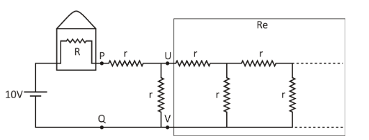
Since there are infinite resistors, if we remove the first two resistors from the front of nodes U and V, as seen in the chart, there would still be infinite resistors. The resistance seen looking to the right would be the same as that seen between P and Q nodes.
The network reduces to the sum of two types of resistances as shown in the figure below:
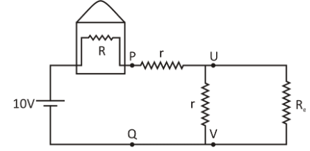
Now, we can write for the infinite resistor network:
${R_{\text{e}}} = r + \dfrac{{r \times {R_{\text{e}}}}}{{r + {R_{\text{e}}}}} \\
\Rightarrow {R_{\text{e}}} - r = \dfrac{{r \times {R_{\text{e}}}}}{{r + {R_{\text{e}}}}} \\
\Rightarrow \left( {{R_{\text{e}}} - r} \right)\left( {r + {R_{\text{e}}}} \right) = r \times {R_{\text{e}}} \\
\Rightarrow R_{\text{e}}^2 - {r^2} - \left( {r \times {R_{\text{e}}}} \right) = 0 \\$
Now, we substitute the required values in it:
$\Rightarrow {24^2} - {r^2} - \left( {r \times 24} \right) = 0 \\
\Rightarrow {r^2} + 24r - 576 = 0 \\
\Rightarrow r = \dfrac{{ - 24 \pm \sqrt {{{24}^2} + 4 \times 576} }}{2} \\$
Since, value of resistance is always positive, so:
$\Rightarrow r = \dfrac{{ - 24 + \sqrt {{{24}^2} + 4 \times 576} }}{2} \\
\Rightarrow r = 14.8\,\Omega $
Hence, the value of \[r\] such that the bulb dissipates about \[1\,{\text{W}}\] of power is \[14.8\,\Omega \] .
The correct option is A.
Note: While solving this problem, most of the students seem to make mistakes while working with the infinite resistors. So, while solving this problem, it is important we should proceed to solve these with proper circuit diagrams, which can minimize a lot of errors. It is also important to recognise the parallel and series connection of the resistors. If the same amount of current flows through the elements, then they are in series.
Formula used:
We have Ohm’s law:
\[V = iR\] …… (1)
Where,
\[V\] indicates voltage.
\[i\] indicates current flowing.
\[R\] indicates resistance.
The power is a circuit is given by:
\[P = {i^2}R\] …… (2)
Where,
\[P\] indicates power in the bulb.
\[i\] indicates current flowing through the bulb.
\[R\] indicates resistance of the bulb.
Complete step by step answer:
In the given question, we are supplied with the following information.There is a light bulb whose resistance is \[16\,\Omega \] .This is connected in series with an infinite resistor network with identical resistors \[r\] .The battery is of \[10\,{\text{V}}\] .We are asked to find the value of \[r\] such that the bulb dissipates about \[1\,{\text{W}}\] of power.
To begin with, we first need to find the total resistance as seen by the battery.So, the net resistance as seen by the battery is given by:
\[{\operatorname{R} _{{\text{net}}}} = R + {R_e}\]
Where,
\[{R_e}\] indicates the external resistance, which is the connection of infinite resistors.
So, the current in the bulb is given by:
\[i = \dfrac{V}{{R + {R_e}}}\] …… (3)
We now substitute the expression for current in the equation (2) and we get:
$P = {i^2}R \\
\Rightarrow P = {\left( {\dfrac{V}{{R + {R_e}}}} \right)^2}R \\$
Now, we will substitute the required values in the above expression just found:
$\Rightarrow 1 = {\left( {\dfrac{{10}}{{16 + {R_e}}}} \right)^2} \times 16 \\
\Rightarrow \dfrac{1}{{16}} = {\left( {\dfrac{{10}}{{16 + {R_e}}}} \right)^2} \\
\Rightarrow \dfrac{1}{4} = \dfrac{{10}}{{16 + {R_e}}} \\
\Rightarrow {R_e} = 24\,\Omega \\$
Now, to calculate the resistance of the infinite resistor, we will again draw the circuit, by mentioning the nodes in it, for better understanding.
Since there are infinite resistors, if we remove the first two resistors from the front of nodes U and V, as seen in the chart, there would still be infinite resistors. The resistance seen looking to the right would be the same as that seen between P and Q nodes.
The network reduces to the sum of two types of resistances as shown in the figure below:
Now, we can write for the infinite resistor network:
${R_{\text{e}}} = r + \dfrac{{r \times {R_{\text{e}}}}}{{r + {R_{\text{e}}}}} \\
\Rightarrow {R_{\text{e}}} - r = \dfrac{{r \times {R_{\text{e}}}}}{{r + {R_{\text{e}}}}} \\
\Rightarrow \left( {{R_{\text{e}}} - r} \right)\left( {r + {R_{\text{e}}}} \right) = r \times {R_{\text{e}}} \\
\Rightarrow R_{\text{e}}^2 - {r^2} - \left( {r \times {R_{\text{e}}}} \right) = 0 \\$
Now, we substitute the required values in it:
$\Rightarrow {24^2} - {r^2} - \left( {r \times 24} \right) = 0 \\
\Rightarrow {r^2} + 24r - 576 = 0 \\
\Rightarrow r = \dfrac{{ - 24 \pm \sqrt {{{24}^2} + 4 \times 576} }}{2} \\$
Since, value of resistance is always positive, so:
$\Rightarrow r = \dfrac{{ - 24 + \sqrt {{{24}^2} + 4 \times 576} }}{2} \\
\Rightarrow r = 14.8\,\Omega $
Hence, the value of \[r\] such that the bulb dissipates about \[1\,{\text{W}}\] of power is \[14.8\,\Omega \] .
The correct option is A.
Note: While solving this problem, most of the students seem to make mistakes while working with the infinite resistors. So, while solving this problem, it is important we should proceed to solve these with proper circuit diagrams, which can minimize a lot of errors. It is also important to recognise the parallel and series connection of the resistors. If the same amount of current flows through the elements, then they are in series.
Recently Updated Pages
Master Class 12 Business Studies: Engaging Questions & Answers for Success
Master Class 12 Chemistry: Engaging Questions & Answers for Success
Master Class 12 Biology: Engaging Questions & Answers for Success
Class 12 Question and Answer - Your Ultimate Solutions Guide
Master Class 11 English: Engaging Questions & Answers for Success
Master Class 11 Social Science: Engaging Questions & Answers for Success
Trending doubts
Which are the Top 10 Largest Countries of the World?
Draw a labelled sketch of the human eye class 12 physics CBSE
Differentiate between homogeneous and heterogeneous class 12 chemistry CBSE
Differentiate between Pyramid of energy and pyramid class 12 biology CBSE
Why is the cell called the structural and functional class 12 biology CBSE
Draw the diagram of the pyramid of energy Explain In class 12 biology CBSE