


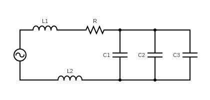
A generator with an adjustable frequency of oscillation is connected to resistance, $ R=100\Omega $ , inductance $ {{L}_{1}}=1.7mH $ and $ {{L}_{2}}=2.3mH $ and capacitances, $ {{C}_{1}}=4\mu F $ , $ {{C}_{2}}=2.5\mu F $ , and $ {{C}_{3}}=3.5\mu F $ . The resonant angular frequency of the circuit is
(A) $ 0.5rad{{s}^{-1}} $
(B) $ 2rad{{s}^{-1}} $
(C) $ 0.5\times {{10}^{4}}rad{{s}^{-1}} $
(D) $ 2\times {{10}^{-4}}rad{{s}^{-1}} $
Answer
533.1k+ views
Hint :To simplify the given arrangement of components, we will find the equivalent value of inductance and capacitance. We know that for both parallel and series RLC circuit, the angular frequency can be found as, $ \omega =\dfrac{1}{\sqrt{LC}} $
Complete Step By Step Answer:
Let us note down the given data,
$ R=100\Omega $ , $ {{L}_{1}}=1.7mH $ , $ {{L}_{2}}=2.3mH $ , $ {{C}_{1}}=4\mu F $ , $ {{C}_{2}}=2.5\mu F $ , $ {{C}_{3}}=3.5\mu F $
Now, let us consider the given figure.
The three capacitors are connected between the same ends i.e. the potential difference on both ends of all capacitors is the same. Thus, the capacitors are proved to be connected In parallel connection.
For the parallel connection of capacitors, the equivalent capacitance can be calculated as
$ {{C}_{eq}}={{C}_{1}}+{{C}_{2}}+{{C}_{3}} $
Substituting the given values,
$ {{C}_{eq}}=4\mu F+2.5\mu F+3.5\mu F $
$ \therefore {{C}_{eq}}=10\mu F $
The modified circuit diagram with equivalent capacitance is as shown below,
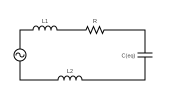
Now, let us rearrange the circuit to get a better understanding of the connection of the inductance
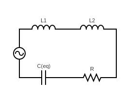
From the rearranged circuit, we can understand that the inductors are connected in a series connection.
For the series connection of inductors, the equivalent inductance can be calculated as,
$ {{L}_{eq}}={{L}_{1}}+{{L}_{2}} $
Substituting the given values,
$ \therefore {{L}_{eq}}=1.7mH+2.3mH $
$ \therefore {{L}_{eq}}=4mH $
Now, we are required to find the resonant angular frequency, which is calculated by the formula
$ \omega =\dfrac{1}{\sqrt{LC}} $
For this specific sum,
$ \therefore \omega =\dfrac{1}{\sqrt{{{L}_{eq}}{{C}_{eq}}}} $
Substituting the obtained values in the equation
$ \therefore \omega =\dfrac{1}{\sqrt{4mH\times 10\mu F}} $
$ \therefore \omega =\dfrac{1}{\sqrt{(4\times {{10}^{-3}}H)\times (10\times {{10}^{-6}}F)}} $
Without considering the units,
$ \therefore \omega =\dfrac{1}{\sqrt{4\times {{10}^{-8}}}} $
$ \therefore \omega =\dfrac{1}{2\times {{10}^{-4}}} $
Shifting the power in the numerator,
$ \therefore \omega =\dfrac{1}{2}\times {{10}^{4}} $
$ \therefore \omega =0.5\times {{10}^{4}}rad{{s}^{-1}} $
The correct answer is Option $ (C) $ .
Note :
The resonant angular frequency is the same for the series as well as the parallel RLC circuit. For the parallel connection of capacitors, the equivalent capacitance is the total capacitance. For the series connection of inductors, the equivalent inductance is the total inductance.
Complete Step By Step Answer:
Let us note down the given data,
$ R=100\Omega $ , $ {{L}_{1}}=1.7mH $ , $ {{L}_{2}}=2.3mH $ , $ {{C}_{1}}=4\mu F $ , $ {{C}_{2}}=2.5\mu F $ , $ {{C}_{3}}=3.5\mu F $
Now, let us consider the given figure.
The three capacitors are connected between the same ends i.e. the potential difference on both ends of all capacitors is the same. Thus, the capacitors are proved to be connected In parallel connection.
For the parallel connection of capacitors, the equivalent capacitance can be calculated as
$ {{C}_{eq}}={{C}_{1}}+{{C}_{2}}+{{C}_{3}} $
Substituting the given values,
$ {{C}_{eq}}=4\mu F+2.5\mu F+3.5\mu F $
$ \therefore {{C}_{eq}}=10\mu F $
The modified circuit diagram with equivalent capacitance is as shown below,
Now, let us rearrange the circuit to get a better understanding of the connection of the inductance
From the rearranged circuit, we can understand that the inductors are connected in a series connection.
For the series connection of inductors, the equivalent inductance can be calculated as,
$ {{L}_{eq}}={{L}_{1}}+{{L}_{2}} $
Substituting the given values,
$ \therefore {{L}_{eq}}=1.7mH+2.3mH $
$ \therefore {{L}_{eq}}=4mH $
Now, we are required to find the resonant angular frequency, which is calculated by the formula
$ \omega =\dfrac{1}{\sqrt{LC}} $
For this specific sum,
$ \therefore \omega =\dfrac{1}{\sqrt{{{L}_{eq}}{{C}_{eq}}}} $
Substituting the obtained values in the equation
$ \therefore \omega =\dfrac{1}{\sqrt{4mH\times 10\mu F}} $
$ \therefore \omega =\dfrac{1}{\sqrt{(4\times {{10}^{-3}}H)\times (10\times {{10}^{-6}}F)}} $
Without considering the units,
$ \therefore \omega =\dfrac{1}{\sqrt{4\times {{10}^{-8}}}} $
$ \therefore \omega =\dfrac{1}{2\times {{10}^{-4}}} $
Shifting the power in the numerator,
$ \therefore \omega =\dfrac{1}{2}\times {{10}^{4}} $
$ \therefore \omega =0.5\times {{10}^{4}}rad{{s}^{-1}} $
The correct answer is Option $ (C) $ .
Note :
The resonant angular frequency is the same for the series as well as the parallel RLC circuit. For the parallel connection of capacitors, the equivalent capacitance is the total capacitance. For the series connection of inductors, the equivalent inductance is the total inductance.
Recently Updated Pages
Master Class 12 Economics: Engaging Questions & Answers for Success
Master Class 12 Physics: Engaging Questions & Answers for Success
Master Class 12 English: Engaging Questions & Answers for Success
Master Class 12 Social Science: Engaging Questions & Answers for Success
Master Class 12 Maths: Engaging Questions & Answers for Success
Master Class 12 Business Studies: Engaging Questions & Answers for Success
Trending doubts
Which are the Top 10 Largest Countries of the World?
What are the major means of transport Explain each class 12 social science CBSE
Draw a labelled sketch of the human eye class 12 physics CBSE
Why cannot DNA pass through cell membranes class 12 biology CBSE
Differentiate between insitu conservation and exsitu class 12 biology CBSE
Draw a neat and well labeled diagram of TS of ovary class 12 biology CBSE