


(a) Explain giving reasons, the basic difference in converting a galvanometer into (i) a voltmeter and (ii) an ammeter.
(b) Two long straight parallel conductors carrying steady currents ${I_1}$and ${I_2}$ are separated by a distance $d$ . Explain briefly, with the help of a suitable diagram, how the magnetic field due to one conductor acts on the other. Hence deduce the expression for the force acting between the two conductors. Mention the nature of this force.
Answer
624.9k+ views
Hint (a) In order to convert galvanometer into voltmeter and ammeter, we have to connect a resistance such that we get maximum voltage and current respectively.
(b) As magnetic force on a current carrying conductor in a uniform magnetic field is given by \[\vec F = I\left( {\vec l \times \vec B} \right)\] where $I$ is the current flowing in the conductor, $l$ is its length and $B$ is the uniform magnetic field, so you have to calculate the magnetic due to each wire.
Magnetic Field Due to Straight Current Carrying Long Conductor is given by $B = \dfrac{{{\mu _0}I}}{{2\pi r}}$ where $r$ is the distance from the wire where the magnetic field is calculated, and $I$ is the applied current.
Complete step-by-step solution:
(a) (i) A galvanometer can be converted into voltmeter by connecting a high resistance called multiplier in series to the galvanometer.
Let $G$ be the resistance of the galvanometer and ${I_g}$, the maximum deflection in the galvanometer. To measure the maximum voltage, $V$ by the voltmeter, the high resistance $R$ is connected in series. So,
$V = {I_g}\left( {R + G} \right)$
On simplifying we have
$R = \dfrac{V}{{{I_g}}} - G$
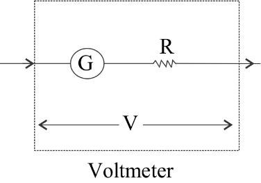
The effective resistance of the voltmeter ${R_v} = R + G$ . Since $R$ is high, the resistance of the voltmeter ${R_v}$ is high and it will draw much current from the circuit.
(ii) A galvanometer can be converted into ammeter by connecting a low resistance called shunt in parallel to the galvanometer.
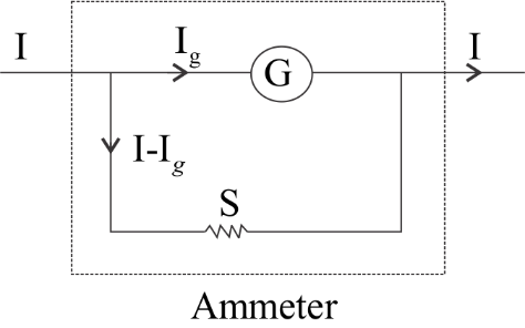
Let $G$ be the resistance of the galvanometer and ${I_g}$, the maximum current that can be passed through the galvanometer. Then $\left( {I - {I_g}} \right)$ is the current passing through the shunt, S.
Since, G and S are in parallel combination
P.D. across S = P.D. across G i.e.
$\left( {I - {I_g}} \right)S = {I_g}G$
On simplifying we have
$S = \dfrac{{{I_g}}}{{I - {I_g}}} \times G$
The effective resistance ${R_A}$ of the ammeter is given by ${R_A} = \dfrac{{GS}}{{G + S}}$ . Since S is low resistance, resistance of ammeter ${R_A}$ is very low and when it is connected in series in the circuits, it will not affect the current passing through the circuit.
(b) The attached figure shows the magnetic field and force between two parallel current carrying wires is shown in the attached figure.
As magnetic force on a current carrying conductor in a uniform magnetic field is given by \[\vec F = I\left( {\vec l \times \vec B} \right)\] where $I$ is the current flowing in the conductor, $l$ is its length and $B$ is the uniform magnetic field, so we have to calculate the magnetic due to each wire first.
As we know that the Magnetic Field Due to Straight Current Carrying Long Conductor is given by $B = \dfrac{{{\mu _0}I}}{{2\pi r}}$ where $r$ is the distance from the wire where the magnetic field is calculated, and $I$ is the applied current.
So, the magnetic field due to the left conductor on the right conductor is given by
\[{B_1} = \dfrac{{{\mu _0}{I_1}}}{{2\pi d}}\]
Now, we consider the length $l$ of the right conductor. So, Magnetic force on the length $l$ of the right conductor is given by
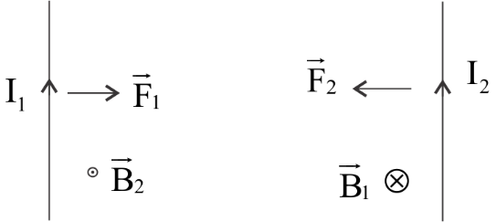
$\Rightarrow {F_2} = {I_2}\left( {l \times {B_1}} \right)$
Now, substituting the value of ${B_1}$ we have
$\Rightarrow {F_2} = \dfrac{{{\mu _0}{I_1}{I_2}l}}{{2\pi d}}$
So, force per unit length of the conductor is given by
\[\Rightarrow \dfrac{{{F_2}}}{l} = \dfrac{{{\mu _0}{I_1}{I_2}}}{{2\pi d}}\]
By similar arguments, it can be shown that
\[\Rightarrow \dfrac{{{F_1}}}{l} = \dfrac{{{\mu _0}{I_1}{I_2}}}{{2\pi d}}\]
This is a non-contact mutual force between the two wires. It is attractive if the directions of current are the same and repulsive if the directions of currents are opposite.
Note:The ammeter must offer low resistance such that it will not change the current passing through it. So ammeter is connected in series to measure the circuit current.
Voltmeter should not draw any current from the circuit otherwise the value of potential difference to be measured will change.
For an infinitely long straight wire, the magnetic field lines are circles centered on the wire. The direction is given by a right-hand rule: With your right hand, point your thumb in the direction of the current. When you curl your fingers they curl in the direction of the magnetic field.
(b) As magnetic force on a current carrying conductor in a uniform magnetic field is given by \[\vec F = I\left( {\vec l \times \vec B} \right)\] where $I$ is the current flowing in the conductor, $l$ is its length and $B$ is the uniform magnetic field, so you have to calculate the magnetic due to each wire.
Magnetic Field Due to Straight Current Carrying Long Conductor is given by $B = \dfrac{{{\mu _0}I}}{{2\pi r}}$ where $r$ is the distance from the wire where the magnetic field is calculated, and $I$ is the applied current.
Complete step-by-step solution:
(a) (i) A galvanometer can be converted into voltmeter by connecting a high resistance called multiplier in series to the galvanometer.
Let $G$ be the resistance of the galvanometer and ${I_g}$, the maximum deflection in the galvanometer. To measure the maximum voltage, $V$ by the voltmeter, the high resistance $R$ is connected in series. So,
$V = {I_g}\left( {R + G} \right)$
On simplifying we have
$R = \dfrac{V}{{{I_g}}} - G$
The effective resistance of the voltmeter ${R_v} = R + G$ . Since $R$ is high, the resistance of the voltmeter ${R_v}$ is high and it will draw much current from the circuit.
(ii) A galvanometer can be converted into ammeter by connecting a low resistance called shunt in parallel to the galvanometer.
Let $G$ be the resistance of the galvanometer and ${I_g}$, the maximum current that can be passed through the galvanometer. Then $\left( {I - {I_g}} \right)$ is the current passing through the shunt, S.
Since, G and S are in parallel combination
P.D. across S = P.D. across G i.e.
$\left( {I - {I_g}} \right)S = {I_g}G$
On simplifying we have
$S = \dfrac{{{I_g}}}{{I - {I_g}}} \times G$
The effective resistance ${R_A}$ of the ammeter is given by ${R_A} = \dfrac{{GS}}{{G + S}}$ . Since S is low resistance, resistance of ammeter ${R_A}$ is very low and when it is connected in series in the circuits, it will not affect the current passing through the circuit.
(b) The attached figure shows the magnetic field and force between two parallel current carrying wires is shown in the attached figure.
As magnetic force on a current carrying conductor in a uniform magnetic field is given by \[\vec F = I\left( {\vec l \times \vec B} \right)\] where $I$ is the current flowing in the conductor, $l$ is its length and $B$ is the uniform magnetic field, so we have to calculate the magnetic due to each wire first.
As we know that the Magnetic Field Due to Straight Current Carrying Long Conductor is given by $B = \dfrac{{{\mu _0}I}}{{2\pi r}}$ where $r$ is the distance from the wire where the magnetic field is calculated, and $I$ is the applied current.
So, the magnetic field due to the left conductor on the right conductor is given by
\[{B_1} = \dfrac{{{\mu _0}{I_1}}}{{2\pi d}}\]
Now, we consider the length $l$ of the right conductor. So, Magnetic force on the length $l$ of the right conductor is given by
$\Rightarrow {F_2} = {I_2}\left( {l \times {B_1}} \right)$
Now, substituting the value of ${B_1}$ we have
$\Rightarrow {F_2} = \dfrac{{{\mu _0}{I_1}{I_2}l}}{{2\pi d}}$
So, force per unit length of the conductor is given by
\[\Rightarrow \dfrac{{{F_2}}}{l} = \dfrac{{{\mu _0}{I_1}{I_2}}}{{2\pi d}}\]
By similar arguments, it can be shown that
\[\Rightarrow \dfrac{{{F_1}}}{l} = \dfrac{{{\mu _0}{I_1}{I_2}}}{{2\pi d}}\]
This is a non-contact mutual force between the two wires. It is attractive if the directions of current are the same and repulsive if the directions of currents are opposite.
Note:The ammeter must offer low resistance such that it will not change the current passing through it. So ammeter is connected in series to measure the circuit current.
Voltmeter should not draw any current from the circuit otherwise the value of potential difference to be measured will change.
For an infinitely long straight wire, the magnetic field lines are circles centered on the wire. The direction is given by a right-hand rule: With your right hand, point your thumb in the direction of the current. When you curl your fingers they curl in the direction of the magnetic field.
Recently Updated Pages
Master Class 12 Business Studies: Engaging Questions & Answers for Success
Master Class 12 Chemistry: Engaging Questions & Answers for Success
Master Class 12 Biology: Engaging Questions & Answers for Success
Class 12 Question and Answer - Your Ultimate Solutions Guide
Master Class 11 English: Engaging Questions & Answers for Success
Master Class 11 Social Science: Engaging Questions & Answers for Success
Trending doubts
Which are the Top 10 Largest Countries of the World?
Draw a labelled sketch of the human eye class 12 physics CBSE
Differentiate between homogeneous and heterogeneous class 12 chemistry CBSE
Differentiate between Pyramid of energy and pyramid class 12 biology CBSE
Why is the cell called the structural and functional class 12 biology CBSE
Draw the diagram of the pyramid of energy Explain In class 12 biology CBSE