


A) Explain briefly the principle on which a transistor-amplifier works as an oscillator. Draw the necessary circuit diagram and explain its working.
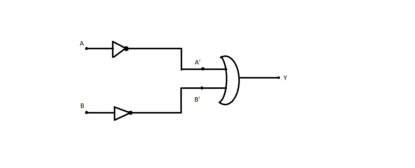
B) Identify the equivalent gate for the following circuit and write its truth table.
Answer
620.4k+ views
Hint: The oscillations in the circuit refer to the electronic amplifier input, and because of the amplifier’s properties, the strength of these oscillations should be supplied to the device to meet the losses. The Boolean algebra for the AND gate is $Y = A \times B.$
Complete step by step solution:
A) The three elements-System or element, Amplifier and Feedback network must be used by an oscillator. The oscillatory circuit or part is composed of an inductive $L$ inductance coil linked to a capacitance $C$ condenser in parallel.
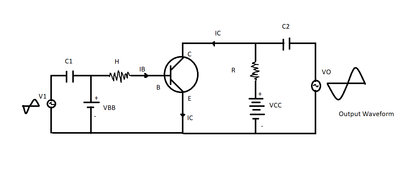
The oscillation frequency on the circuit depends on $L$ and $C$ values. Electronic amplifiers accept a dc power from the battery or dc power supply and transform it into an AC power supply for the petrol system.
The expression of frequency is given by
$f = \dfrac{1}{{2\pi \sqrt {LC}}}$
Where inductance of coil in henrys is $L$ and $C$ is the capacitance of capacitor in farads.
The AC is a power supply unit. The input of the electronic amplifier is susceptible to swings occurring on the circuit. We get improved output of these oscillations due to the amplifying properties of the amplifier. Dc input from an external source (a battery or power supply) is responsible for this increased output of the oscillations. The power of the amplifier to meet the losses can be delivered to the tank circuit. In order to assist oscillation, the feedback network gives the tank or oscillatory device a portion of its output power in the correct step. This means that there is strong feedback on the Feedback circuit.
B) The following circuit is equal to the AND gate and its Truth Table below
The Boolean algebra for the AND gate is $Y = A \times B$
Note: If the tank (or oscillatory) and feedback circuits are compatible with it, a transistor may be worked as an oscillator to produce continuous undammed oscillations at either desired frequency. Both oscillators have a similar purpose under distinct names, i.e. they produce continuous undammed output. In terms of energy supply to a tank or oscillatory circuit, however, the approaches are distinct in order to satisfy losses and frequency ranges.
Complete step by step solution:
A) The three elements-System or element, Amplifier and Feedback network must be used by an oscillator. The oscillatory circuit or part is composed of an inductive $L$ inductance coil linked to a capacitance $C$ condenser in parallel.
The oscillation frequency on the circuit depends on $L$ and $C$ values. Electronic amplifiers accept a dc power from the battery or dc power supply and transform it into an AC power supply for the petrol system.
The expression of frequency is given by
$f = \dfrac{1}{{2\pi \sqrt {LC}}}$
Where inductance of coil in henrys is $L$ and $C$ is the capacitance of capacitor in farads.
The AC is a power supply unit. The input of the electronic amplifier is susceptible to swings occurring on the circuit. We get improved output of these oscillations due to the amplifying properties of the amplifier. Dc input from an external source (a battery or power supply) is responsible for this increased output of the oscillations. The power of the amplifier to meet the losses can be delivered to the tank circuit. In order to assist oscillation, the feedback network gives the tank or oscillatory device a portion of its output power in the correct step. This means that there is strong feedback on the Feedback circuit.
B) The following circuit is equal to the AND gate and its Truth Table below
The Boolean algebra for the AND gate is $Y = A \times B$
| Input | Input | Output |
| $A$ | $B$ | $Y$ |
| $0$ | $0$ | $0$ |
| $0$ | $1$ | $0$ |
| $1$ | $0$ | $0$ |
| $1$ | $1$ | $1$ |
Note: If the tank (or oscillatory) and feedback circuits are compatible with it, a transistor may be worked as an oscillator to produce continuous undammed oscillations at either desired frequency. Both oscillators have a similar purpose under distinct names, i.e. they produce continuous undammed output. In terms of energy supply to a tank or oscillatory circuit, however, the approaches are distinct in order to satisfy losses and frequency ranges.
Recently Updated Pages
Master Class 12 Business Studies: Engaging Questions & Answers for Success
Master Class 12 Chemistry: Engaging Questions & Answers for Success
Master Class 12 Biology: Engaging Questions & Answers for Success
Class 12 Question and Answer - Your Ultimate Solutions Guide
Master Class 11 English: Engaging Questions & Answers for Success
Master Class 11 Social Science: Engaging Questions & Answers for Success
Trending doubts
Which are the Top 10 Largest Countries of the World?
Draw a labelled sketch of the human eye class 12 physics CBSE
Differentiate between homogeneous and heterogeneous class 12 chemistry CBSE
Differentiate between Pyramid of energy and pyramid class 12 biology CBSE
Why is the cell called the structural and functional class 12 biology CBSE
Draw the diagram of the pyramid of energy Explain In class 12 biology CBSE