


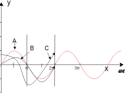
A device X is connected to an ac source $V = {V_0}\sin \omega t$. The variation of voltage, current and power in one cycle is shown in the graph (see figure).
a) Identify the device X
b) Which of the curves A, B and C represent the voltage, current and the power consumed in the circuit? Justify your answer.
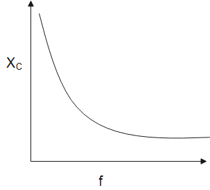
c) How does its impedance vary with frequency of the ac source? Show graphically.
d) How does its impedance vary with frequency of the ac source? Show graphically.
Answer
600.9k+ views
Hint: In this question, we know that a LCR circuit is an electrical circuit. Here, we will see the basics behind the LCR circuit and further study about the relation between the given current, voltage, capacitance and impedance. So, this will help us get the required answer.
Formula used:
$\eqalign{& I = \dfrac{{dQ}}{{dt}} \cr
& Q = CV \cr} $
${X_C} \propto \dfrac{1}{f}$
Complete step by step solution:
a) As we know the average power of a device is zero. So, the power factor$\cos \varphi = 0$ i.e., $\varphi = {90^ \circ }$. Also, we know that the change in phase between current and voltage is in the inductor or the capacitor. So the devices that may be present are either capacitor or inductor or it can be the combination of both inductor and capacitor.
b) Here, the curve A represents the power, which is given by: P=VI, where we get the amplitude that is equivalent to the multiplication of amplitudes of voltage V and current I curve. Also, from curve B, we observe that the sine curve represents the voltage, whereas the curve C is a cosine curve which represents the current. Now, we already know that the full cycle of the graph consists of two positive and two negative symmetrical areas. So, the average power that is consumed in the given circuit is zero.
c) As we know that the AC impedance of a capacitor is known to us as reactance and as we know in the capacitor circuits, which are more commonly called as capacitive Reactance, given by ${X_C}$. Below is a graph that shows the variation of capacitive reactance with frequency.
${X_C} \propto \dfrac{1}{f}$
d) Voltage applied to the circuit is $V = {V_0}\sin \omega t$, as we can see due to the given voltage V, a charge will be produced and this charge will charge the plates of the capacitor with positive and negative charges.
V= CQ
Q= CV
So , the instantaneous value of the current I in the given circuit is given by:
$I = \dfrac{{dQ}}{{dt}} = \dfrac{{d(CV)}}{{dt}}$
Now, putting the given value of voltage V, in the above equation, we get:
$I = \dfrac{{d(C{V_0}\sin \omega t)}}{{dt}}$
$\eqalign{& \Rightarrow I = \omega C{V_0}\sin \omega t \cr
& \Rightarrow I = \dfrac{{{V_0}}}{{\dfrac{1}{{\omega C}}}}\sin \left( {\omega t + \dfrac{\pi }{2}} \right) \cr} $
$\therefore I = {I_0}\sin \left( {\omega t + \dfrac{\pi }{2}} \right)$
$here,{I_0} = \dfrac{{{V_0}}}{{\dfrac{1}{{\omega C}}}}$
So, we can say that current leads the voltage by a phase difference of $\pi /2$
Therefore, we get the required results of all the given questions.
Additional information:
As we know resistance, Inductance, and Capacitance have very different phase relationships to each other when connected to a sinusoidal alternating supply.
A capacitor consists of two or more parallel conductive or metal plates. These plates are not connected to each other, but here they are electrically separated either by air or by some form of an insulating material, for example- waxed paper, mica, ceramic, plastic or some form of the liquid gel are used in electrolytic capacitors. This insulating layer between capacitor’s plates is commonly called the Dielectric.
Note:
Here, we should note that capacitance is measured in Farad, or can be said as one coulomb per volt. Capacitance is dependent on the dielectric constant as well as on the distance between the two plates. Also, we should know that a parallel plate capacitor is the simplest form of a capacitor.
Recently Updated Pages
Master Class 12 Business Studies: Engaging Questions & Answers for Success
Master Class 12 Chemistry: Engaging Questions & Answers for Success
Master Class 12 Biology: Engaging Questions & Answers for Success
Class 12 Question and Answer - Your Ultimate Solutions Guide
Master Class 11 English: Engaging Questions & Answers for Success
Master Class 11 Social Science: Engaging Questions & Answers for Success
Trending doubts
Which are the Top 10 Largest Countries of the World?
The total number of vertebrae in man is a30 b31 c32 class 12 biology CBSE
Draw a labelled sketch of the human eye class 12 physics CBSE
The number of cranial nerves in a frog is A 10 pairs class 12 biology CBSE
Differentiate between homogeneous and heterogeneous class 12 chemistry CBSE
Differentiate between Pyramid of energy and pyramid class 12 biology CBSE