


(a) Determine the value of phase difference between the current and the voltage in the given series LCR circuit.
(b) Calculate the value of the additional capacitor which may be joined suitably to the capacitor C that would make the power factor unity.
Answer
622.8k+ views
Hint: In this problem, we must remember the formula of phase difference in a series LCR circuit $\tan \phi =\dfrac{{{\chi }_{L}}-{{\chi }_{C}}}{R}$, where $\phi $ is the phase difference and ${{\chi }_{L}},{{\chi }_{C}}$
refer to the impedances of inductor and capacitor respectively. The power factor of a series LCR circuit is given by\[\cos \phi \].
Basic knowledge of net capacitance, when capacitors are in series case and as well as when the capacitors are in parallel case must be known too.
Step by step solution:
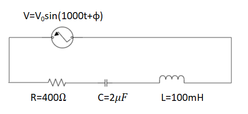
The problem consists of a series LCR circuit, where the alternating voltage in the circuit is given by, $V={{V}_{0}}\sin (1000t+\phi )$. The resistance value of the resistor connected is$R=400\Omega $. The inductance value of the inductor connected in the circuit is $L=100mH=100\times {{10}^{-3}}H$ and the capacitance value of the capacitor connected in the circuit is $C=2\mu F=2\times {{10}^{-6}}F$.
Since, the alternating voltage source already shows a phase difference, hence, the impedances ${{\chi }_{L}},{{\chi }_{C}}$ and R are also out of phase with each other. The relation between these three impedances is given by the Impedance triangle for the series LCR circuit as shown below.
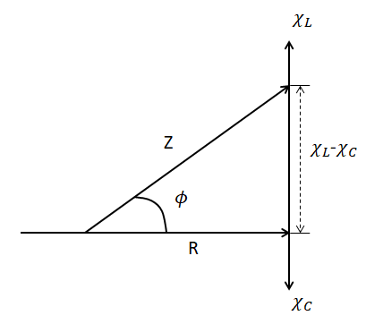
Since, it is a right angled triangle, with the hypotenuse being total impedance of the circuit Z.
Therefore, ${{Z}^{2}}={{R}^{2}}+{{({{\chi }_{L}}-{{\chi }_{C}})}^{2}}$. Hence the total impedance becomes, $Z=\sqrt{{{R}^{2}}+{{({{\chi }_{L}}-{{\chi }_{C}})}^{2}}}$.
We know the impedance of inductance is, ${{\chi }_{L}}=\omega L$ and the impedance of the capacitor is given by, ${{\chi }_{C}}=\dfrac{1}{\omega C}$. This makes the value of impedance to become, $Z=\sqrt{{{R}^{2}}+{{(\omega L-\dfrac{1}{\omega C})}^{2}}}$.
Therefore, the phase angle $\phi $, also known as the phase difference can be found out using the trigonometric identities. $\cos \phi =\dfrac{R}{Z}$, $\sin \phi =\dfrac{{{\chi }_{L}}-{{\chi }_{C}}}{Z}$ and $\tan \phi =\dfrac{{{\chi }_{L}}-{{\chi }_{C}}}{R}$.
The most preferred way to find out the value of the phase angle is using the formula, $\tan \phi =\dfrac{{{\chi }_{L}}-{{\chi }_{C}}}{R}\Rightarrow \phi ={{\tan }^{-1}}(\dfrac{{{\chi }_{L}}-{{\chi }_{C}}}{R})$.
We are given that $V={{V}_{0}}\sin (1000t+\phi )$. Comparing this value of the alternating voltage against the general formula, $V={{V}_{0}}\sin (\omega t+\phi )$, we find that the value of the angular frequency$(\omega )$is 1000. Therefore, the inductive impedance becomes, ${{\chi }_{L}}=\omega L=1000\times 100\times {{10}^{-3}}\Omega \Rightarrow {{\chi }_{L}}=100\Omega $. Similarly, the capacitive impedance becomes, ${{\chi }_{C}}=\dfrac{1}{\omega C}=\dfrac{1}{1000\times 2\times {{10}^{-6}}}\Rightarrow {{\chi }_{C}}=500\Omega $.
Substituting in these values of inductive impedance and capacitive impedance, along with the known value of resistor’s resistance ($R=400\Omega $) into the equation to find the phase angle we get, $\phi ={{\tan }^{-1}}(\dfrac{{{\chi }_{L}}-{{\chi }_{C}}}{R})\Rightarrow \phi ={{\tan }^{-1}}(\dfrac{100-500}{400})\Rightarrow \phi ={{\tan }^{-1}}(\dfrac{-400}{400})\Rightarrow \phi ={{\tan }^{-1}}(-1)$
We know that${{\tan }^{-1}}(-1)=\dfrac{-\pi }{4}=-{{45}^{0}}$, this implies$\phi =\dfrac{-\pi }{4}=-{{45}^{0}}.$ Therefore the phase difference between the current and voltage is $-{{45}^{0}}$.
Let’s find the power factor now. The power factor is the ratio of the resistor’s resistance (R) and the net impedance of the series LCR circuit (Z). This ratio can also be found out using the impedance triangle as, $\cos \phi =\dfrac{R}{Z}$.
In the question, it is given that the power factor is unity (1), therefore R=Z. This implies, $R=Z\Rightarrow R=\sqrt{{{R}^{2}}+{{(\omega L-\dfrac{1}{\omega C})}^{2}}}$. For the condition to be true, the inductive impedance and the capacitive impedance must be equal. Therefore, $\omega L=\dfrac{1}{\omega C}\Rightarrow {{\omega }^{2}}=\dfrac{1}{LC}$. Putting in the values of the angular frequency and the inductance value into the equation, we get, ${{\omega }^{2}}=\dfrac{1}{LC}\Rightarrow {{(1000)}^{2}}=\dfrac{1}{(100\times {{10}^{-3}})C}\Rightarrow C=\dfrac{1}{{{10}^{6}}\times {{10}^{-1}}}\Rightarrow C={{10}^{-5}}F$.
Since, the new capacitance value is greater than the capacitance value already in the circuit, we will have to put an additional capacitor of capacitance $({{C}_{1}})$ in parallel to the capacitor in the circuit.
We know that the net capacitance of 2 capacitors in parallel is given by, ${{C}_{net}}={{C}_{1}}+{{C}_{2}}$. Similarly, in this case, for the new capacitance $C={{10}^{-5}}F$ using the capacitance in the circuit $C=2\mu F=2\times {{10}^{-6}}F$ and the new capacitance $({{C}_{1}})$ in parallel to it, we get, \[{{C}_{net}}={{C}_{1}}+{{C}_{2}}\Rightarrow {{10}^{-5}}F=0.2\times {{10}^{-5}}F+{{C}_{1}}\Rightarrow {{C}_{1}}=1\times {{10}^{-5}}F-0.2\times {{10}^{-5}}F\]
That is the additional capacitance to be added in parallel to the initial one is, \[{{C}_{1}}=0.8\times {{10}^{-5}}F=8\times {{10}^{-6}}F=8\mu F.\]
Note:
The phase angle \[(\phi )\] in the impedance triangle diagram can be both positive and negative. When the phase angle is positive, then the voltage leads the current by the phase angle and when the value of the phase angle is negative, the current leads voltage leads voltage by the phase angle.
Hence, for the phase angle that we found out, $\phi =\dfrac{-\pi }{4}=-{{45}^{0}}.$ Current leads voltage by angle of \[{{45}^{0}}\].
refer to the impedances of inductor and capacitor respectively. The power factor of a series LCR circuit is given by\[\cos \phi \].
Basic knowledge of net capacitance, when capacitors are in series case and as well as when the capacitors are in parallel case must be known too.
Step by step solution:
The problem consists of a series LCR circuit, where the alternating voltage in the circuit is given by, $V={{V}_{0}}\sin (1000t+\phi )$. The resistance value of the resistor connected is$R=400\Omega $. The inductance value of the inductor connected in the circuit is $L=100mH=100\times {{10}^{-3}}H$ and the capacitance value of the capacitor connected in the circuit is $C=2\mu F=2\times {{10}^{-6}}F$.
Since, the alternating voltage source already shows a phase difference, hence, the impedances ${{\chi }_{L}},{{\chi }_{C}}$ and R are also out of phase with each other. The relation between these three impedances is given by the Impedance triangle for the series LCR circuit as shown below.
Since, it is a right angled triangle, with the hypotenuse being total impedance of the circuit Z.
Therefore, ${{Z}^{2}}={{R}^{2}}+{{({{\chi }_{L}}-{{\chi }_{C}})}^{2}}$. Hence the total impedance becomes, $Z=\sqrt{{{R}^{2}}+{{({{\chi }_{L}}-{{\chi }_{C}})}^{2}}}$.
We know the impedance of inductance is, ${{\chi }_{L}}=\omega L$ and the impedance of the capacitor is given by, ${{\chi }_{C}}=\dfrac{1}{\omega C}$. This makes the value of impedance to become, $Z=\sqrt{{{R}^{2}}+{{(\omega L-\dfrac{1}{\omega C})}^{2}}}$.
Therefore, the phase angle $\phi $, also known as the phase difference can be found out using the trigonometric identities. $\cos \phi =\dfrac{R}{Z}$, $\sin \phi =\dfrac{{{\chi }_{L}}-{{\chi }_{C}}}{Z}$ and $\tan \phi =\dfrac{{{\chi }_{L}}-{{\chi }_{C}}}{R}$.
The most preferred way to find out the value of the phase angle is using the formula, $\tan \phi =\dfrac{{{\chi }_{L}}-{{\chi }_{C}}}{R}\Rightarrow \phi ={{\tan }^{-1}}(\dfrac{{{\chi }_{L}}-{{\chi }_{C}}}{R})$.
We are given that $V={{V}_{0}}\sin (1000t+\phi )$. Comparing this value of the alternating voltage against the general formula, $V={{V}_{0}}\sin (\omega t+\phi )$, we find that the value of the angular frequency$(\omega )$is 1000. Therefore, the inductive impedance becomes, ${{\chi }_{L}}=\omega L=1000\times 100\times {{10}^{-3}}\Omega \Rightarrow {{\chi }_{L}}=100\Omega $. Similarly, the capacitive impedance becomes, ${{\chi }_{C}}=\dfrac{1}{\omega C}=\dfrac{1}{1000\times 2\times {{10}^{-6}}}\Rightarrow {{\chi }_{C}}=500\Omega $.
Substituting in these values of inductive impedance and capacitive impedance, along with the known value of resistor’s resistance ($R=400\Omega $) into the equation to find the phase angle we get, $\phi ={{\tan }^{-1}}(\dfrac{{{\chi }_{L}}-{{\chi }_{C}}}{R})\Rightarrow \phi ={{\tan }^{-1}}(\dfrac{100-500}{400})\Rightarrow \phi ={{\tan }^{-1}}(\dfrac{-400}{400})\Rightarrow \phi ={{\tan }^{-1}}(-1)$
We know that${{\tan }^{-1}}(-1)=\dfrac{-\pi }{4}=-{{45}^{0}}$, this implies$\phi =\dfrac{-\pi }{4}=-{{45}^{0}}.$ Therefore the phase difference between the current and voltage is $-{{45}^{0}}$.
Let’s find the power factor now. The power factor is the ratio of the resistor’s resistance (R) and the net impedance of the series LCR circuit (Z). This ratio can also be found out using the impedance triangle as, $\cos \phi =\dfrac{R}{Z}$.
In the question, it is given that the power factor is unity (1), therefore R=Z. This implies, $R=Z\Rightarrow R=\sqrt{{{R}^{2}}+{{(\omega L-\dfrac{1}{\omega C})}^{2}}}$. For the condition to be true, the inductive impedance and the capacitive impedance must be equal. Therefore, $\omega L=\dfrac{1}{\omega C}\Rightarrow {{\omega }^{2}}=\dfrac{1}{LC}$. Putting in the values of the angular frequency and the inductance value into the equation, we get, ${{\omega }^{2}}=\dfrac{1}{LC}\Rightarrow {{(1000)}^{2}}=\dfrac{1}{(100\times {{10}^{-3}})C}\Rightarrow C=\dfrac{1}{{{10}^{6}}\times {{10}^{-1}}}\Rightarrow C={{10}^{-5}}F$.
Since, the new capacitance value is greater than the capacitance value already in the circuit, we will have to put an additional capacitor of capacitance $({{C}_{1}})$ in parallel to the capacitor in the circuit.
We know that the net capacitance of 2 capacitors in parallel is given by, ${{C}_{net}}={{C}_{1}}+{{C}_{2}}$. Similarly, in this case, for the new capacitance $C={{10}^{-5}}F$ using the capacitance in the circuit $C=2\mu F=2\times {{10}^{-6}}F$ and the new capacitance $({{C}_{1}})$ in parallel to it, we get, \[{{C}_{net}}={{C}_{1}}+{{C}_{2}}\Rightarrow {{10}^{-5}}F=0.2\times {{10}^{-5}}F+{{C}_{1}}\Rightarrow {{C}_{1}}=1\times {{10}^{-5}}F-0.2\times {{10}^{-5}}F\]
That is the additional capacitance to be added in parallel to the initial one is, \[{{C}_{1}}=0.8\times {{10}^{-5}}F=8\times {{10}^{-6}}F=8\mu F.\]
Note:
The phase angle \[(\phi )\] in the impedance triangle diagram can be both positive and negative. When the phase angle is positive, then the voltage leads the current by the phase angle and when the value of the phase angle is negative, the current leads voltage leads voltage by the phase angle.
Hence, for the phase angle that we found out, $\phi =\dfrac{-\pi }{4}=-{{45}^{0}}.$ Current leads voltage by angle of \[{{45}^{0}}\].
Recently Updated Pages
Master Class 12 Business Studies: Engaging Questions & Answers for Success
Master Class 12 Biology: Engaging Questions & Answers for Success
Master Class 12 Chemistry: Engaging Questions & Answers for Success
Class 12 Question and Answer - Your Ultimate Solutions Guide
Master Class 11 Social Science: Engaging Questions & Answers for Success
Master Class 11 English: Engaging Questions & Answers for Success
Trending doubts
Which are the Top 10 Largest Countries of the World?
Draw a labelled sketch of the human eye class 12 physics CBSE
Differentiate between homogeneous and heterogeneous class 12 chemistry CBSE
Sulphuric acid is known as the king of acids State class 12 chemistry CBSE
Why is the cell called the structural and functional class 12 biology CBSE
Which is the correct genotypic ratio of mendel dihybrid class 12 biology CBSE