


Write the logic symbols and prepare the truth tables of the following gates.
(1) AND
(2) NOR
Answer
587.7k+ views
Hint
A table that is used to show the Boolean or logic expression of a logic gate is referred to as a truth table. It represents the resultant output states corresponding to each input state.
Complete step by step answer
(1) AND gate:
An AND gate is a basic logic gate in which the resultant output is high or true only if all the input values are high or true. We consider a two-input AND gate such that ‘X’ and ‘Y’ represents the input states and the resultant output corresponding to the combination of the input states is represented by ‘R’ as shown in the figure.
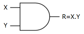
The input state values can be specified in the form of bit values, i.e. 0 that represents low or false state and 1 that represents a high or true state. The resultant output in the case of AND gate will be high that is 1 only when both the input values are low that is 0. The truth table representing the two-input AND gate is shown below.
The logic expression for AND gate according to the truth table will be represented by the logical multiplication of the inputs, X and Y to give the resultant such that,
${\rm{R}} = {\rm{X}}.{\rm{Y}}$
(2) NOR gate:
A NOR gate is a universal logic gate in which the resultant output is high or true only if all the input values are low or false. We consider a two-input NOR gate such that ‘X’ and ‘Y’ represents the input states and the resultant output corresponding the combination of the input states is represented by
‘R’ as shown in the figure.
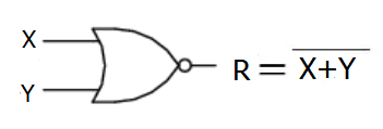
The input state values can be specified in the form of bit values, i.e. 0 that represents low or false state and 1 that represents a high or true state. The resultant output in the case of the NOR gate will be a high value that is 1 only when both the input values are low that is 0. The output will be low even if one of the input values is high. The truth table representing the two-input NOR gate is shown below.
The logic expression for NOR gate according to the truth table will be represented by the negation of logical addition of the inputs, X and Y to give the resultant output such that,
${\rm{R}} = \overline {{\rm{X}} + {\rm{Y}}} $
Note
The logical symbol of the NOR gate must not be confused with the symbol for the OR gate. The NOR gate symbol consists of an inverter represented in the form of a bubble such that the operation of this gate is opposite to that of an OR gate.
A table that is used to show the Boolean or logic expression of a logic gate is referred to as a truth table. It represents the resultant output states corresponding to each input state.
Complete step by step answer
(1) AND gate:
An AND gate is a basic logic gate in which the resultant output is high or true only if all the input values are high or true. We consider a two-input AND gate such that ‘X’ and ‘Y’ represents the input states and the resultant output corresponding to the combination of the input states is represented by ‘R’ as shown in the figure.
The input state values can be specified in the form of bit values, i.e. 0 that represents low or false state and 1 that represents a high or true state. The resultant output in the case of AND gate will be high that is 1 only when both the input values are low that is 0. The truth table representing the two-input AND gate is shown below.
| X | Y | R |
| 1 | 1 | 1 |
| 1 | 0 | 0 |
| 0 | 1 | 0 |
| 0 | 0 | 0 |
The logic expression for AND gate according to the truth table will be represented by the logical multiplication of the inputs, X and Y to give the resultant such that,
${\rm{R}} = {\rm{X}}.{\rm{Y}}$
(2) NOR gate:
A NOR gate is a universal logic gate in which the resultant output is high or true only if all the input values are low or false. We consider a two-input NOR gate such that ‘X’ and ‘Y’ represents the input states and the resultant output corresponding the combination of the input states is represented by
‘R’ as shown in the figure.
The input state values can be specified in the form of bit values, i.e. 0 that represents low or false state and 1 that represents a high or true state. The resultant output in the case of the NOR gate will be a high value that is 1 only when both the input values are low that is 0. The output will be low even if one of the input values is high. The truth table representing the two-input NOR gate is shown below.
| X | Y | R |
| 1 | 1 | 0 |
| 1 | 0 | 0 |
| 0 | 1 | 0 |
| 0 | 0 | 1 |
The logic expression for NOR gate according to the truth table will be represented by the negation of logical addition of the inputs, X and Y to give the resultant output such that,
${\rm{R}} = \overline {{\rm{X}} + {\rm{Y}}} $
Note
The logical symbol of the NOR gate must not be confused with the symbol for the OR gate. The NOR gate symbol consists of an inverter represented in the form of a bubble such that the operation of this gate is opposite to that of an OR gate.
Recently Updated Pages
Master Class 10 Computer Science: Engaging Questions & Answers for Success
Master Class 10 General Knowledge: Engaging Questions & Answers for Success
Master Class 10 English: Engaging Questions & Answers for Success
Master Class 10 Social Science: Engaging Questions & Answers for Success
Master Class 10 Maths: Engaging Questions & Answers for Success
Master Class 10 Science: Engaging Questions & Answers for Success
Trending doubts
What is the median of the first 10 natural numbers class 10 maths CBSE
Which women's tennis player has 24 Grand Slam singles titles?
Who is the Brand Ambassador of Incredible India?
Why is there a time difference of about 5 hours between class 10 social science CBSE
Write a letter to the principal requesting him to grant class 10 english CBSE
A moving boat is observed from the top of a 150 m high class 10 maths CBSE