


Write the logic symbol and truth table of NAND gate.
Answer
645.3k+ views
Hint: The logic gate is used to implement the Boolean’s function. In logic gates the logical operations are performed using binary input. More than one binary input is converted into the single binary input using a logic gate.
Complete step by step answer:
A NAND gate can have two or three inputs. Using the combination of these inputs one single output is obtained using the NAND gate.
The simple NAND gate uses diodes and transistors in its construction. The resistor transistor switches are used in the construction of the NAND gate. The switches are connected in the input of the NAND gate. The input is given to the base of the transistor. Two transistors are used in the circuit diagram of the NAND gate. The
The logic NAND gate is the combination of the NOT and AND gate. The input of the AND gate is inverted using the NOT gate in the NAND gate. So, the output is also modified from the AND gate.
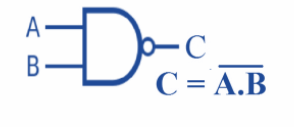
Logic symbol for two input NAND gate:
Truth table for two input NAND gate:
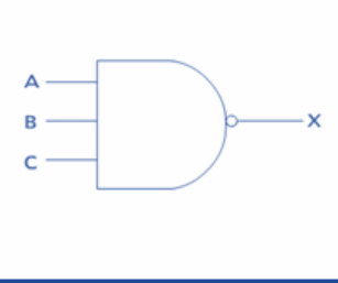
Logic symbol for three input NAND gate:
Truth table for three input NAND gate:
Note:
Another method:
The NAND gate can be constructed using AND gate:
The truth table for AND gate is given as:
Truth table for two input NAND gate:
Complete step by step answer:
A NAND gate can have two or three inputs. Using the combination of these inputs one single output is obtained using the NAND gate.
The simple NAND gate uses diodes and transistors in its construction. The resistor transistor switches are used in the construction of the NAND gate. The switches are connected in the input of the NAND gate. The input is given to the base of the transistor. Two transistors are used in the circuit diagram of the NAND gate. The
The logic NAND gate is the combination of the NOT and AND gate. The input of the AND gate is inverted using the NOT gate in the NAND gate. So, the output is also modified from the AND gate.
Logic symbol for two input NAND gate:
Truth table for two input NAND gate:
| A | B | NAND OUTPUT |
| 0 | 0 | 1 |
| 0 | 1 | 1 |
| 1 | 0 | 1 |
| 1 | 1 | 0 |
Logic symbol for three input NAND gate:
Truth table for three input NAND gate:
| A | B | C | NAND OUTPUT |
| 0 | 0 | 0 | 1 |
| 0 | 0 | 1 | 1 |
| 0 | 1 | 0 | 1 |
| 0 | 1 | 1 | 1 |
| 1 | 0 | 0 | 1 |
| 1 | 0 | 1 | 1 |
| 1 | 1 | 0 | 1 |
| 1 | 1 | 1 | 0 |
Note:
Another method:
The NAND gate can be constructed using AND gate:
The truth table for AND gate is given as:
Truth table for two input NAND gate:
| A | B | AND OUTPUT | NANDOUTPUT |
| 0 | 0 | 0 | 1 |
| 0 | 1 | 0 | 1 |
| 1 | 0 | 0 | 1 |
| 1 | 1 | 1 | 0 |
Recently Updated Pages
Basicity of sulphurous acid and sulphuric acid are
Master Class 12 Economics: Engaging Questions & Answers for Success
Master Class 12 Biology: Engaging Questions & Answers for Success
Master Class 11 English: Engaging Questions & Answers for Success
Master Class 11 Physics: Engaging Questions & Answers for Success
Master Class 11 Computer Science: Engaging Questions & Answers for Success
Trending doubts
Draw a labelled sketch of the human eye class 12 physics CBSE
The chemical formula of tear gas is A CO Cl 2 B C 10 class 12 chemistry CBSE
Draw ray diagrams each showing i myopic eye and ii class 12 physics CBSE
Which are the Top 10 Largest Countries of the World?
Differentiate between homogeneous and heterogeneous class 12 chemistry CBSE
Which is the correct genotypic ratio of mendel dihybrid class 12 biology CBSE