


With the help of a circuit diagram, explain the working of a Colpitt’s oscillator.
Answer
605.4k+ views
Hint: An oscillatory circuit, also called a tank circuit is an electronic circuit that produces a repetitive waveform with a constant amplitude and frequency and the oscillator does not require an external input signal. The tank circuit of a Colpitt’s oscillator consists of two capacitors in series and an inductance coil connected parallel to them.
Formulas used:
The frequency of oscillations of a tank circuit is given by, $f = \dfrac{1}{{2\pi \sqrt {LC} }}$ where $L$ is the inductance of the inductor coil and $C$ is the capacitance of the tank circuit.
The effective capacitance of two capacitors $C_1$ and $C_2$ connected in series is given by, $\dfrac{1}{C} = \dfrac{1}{{C_1}} + \dfrac{1}{{C_2}}$.
Complete Step by Step Answer:
Step 1: Sketching the circuit diagram of the Colpitt’s oscillator.
Step 2: Listing the elements of the circuit.
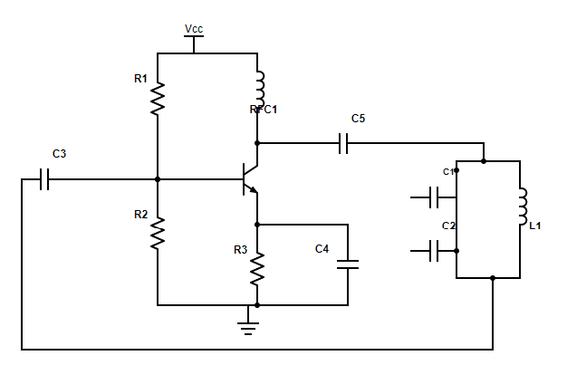
The tank circuit is made up of the two capacitors $C_{1}$ and $C_{2}$ in series and connected parallel to the inductor $L_{1}$.
Between the collector and the $ + V_{cc}$ , a radio frequency choke $RFC_{1}$ is connected. The $RFC_{1}$ acts as a collector load and ensures proper bias to the collector. All ac signals that could be present in the power supply are also decoupled by the radio frequency choke.
The resistors $R_{1}$ and $R_{2}$ form the voltage divider component of the circuit.
The collector capacitor $C_{5}$ couples the oscillatory circuit to the collector, the base capacitor $C_{3}$ blocks the dc currents from entering the base and the emitter capacitor $C_{4}$ bypasses the emitter resistance $R_{2}$.
Step 3: Explanation of the working of the circuit.
The capacitors $C_{1}$ and $C_{2}$ get charged when we switch on the circuit. They discharge through the inductance coil $L_{1}$. An oscillatory current is then produced. The oscillations across $C_{2}$ are feedback to the input of the circuit. The input given to the transistor gets amplified. The output of the transistor will be received across the capacitor $C_{1}$. The process then repeats and leads to the generation of a sustained oscillating output across the secondary coil of the transformer. The primary coil of the transformer is the inductance coil $L_1$.
The frequency of the oscillations of the output will match the natural frequency of the oscillatory circuit (or tank circuit).
The frequency of the tank circuit is given by, $f = \dfrac{1}{{2\pi \sqrt {L_1 \times C} }}$
where $L_1$ is the inductance of the inductor coil and $C$ is the effective capacitance of the capacitors connected in series.
We have the effective capacitance of the tank circuit as $\dfrac{1}{C} = \dfrac{1}{{C_1}} + \dfrac{1}{{C_2}}$.
On simplifying the above expression we get, $C = \dfrac{{C_1C_2}}{{C_1 + C_2}}$
Thus the frequency of the oscillations will be $f = \dfrac{1}{{2\pi \sqrt {L_1 \times \left( {\dfrac{{C_1C_2}}{{C_1 + C_2}}} \right)}}}$
Note:
For an oscillator, the phase difference between the output signal and the input signal must be 0° or 360°. This is referred to as positive feedback. There exists a phase difference of 180° between the output and the input as the ends of the tank circuit are oppositely charged. Also, the transistor used as an amplifier again produces a phase shift of 180° between the output and the input. Thus the total phase difference between the output and input will be 360°.
Formulas used:
The frequency of oscillations of a tank circuit is given by, $f = \dfrac{1}{{2\pi \sqrt {LC} }}$ where $L$ is the inductance of the inductor coil and $C$ is the capacitance of the tank circuit.
The effective capacitance of two capacitors $C_1$ and $C_2$ connected in series is given by, $\dfrac{1}{C} = \dfrac{1}{{C_1}} + \dfrac{1}{{C_2}}$.
Complete Step by Step Answer:
Step 1: Sketching the circuit diagram of the Colpitt’s oscillator.
Step 2: Listing the elements of the circuit.
The tank circuit is made up of the two capacitors $C_{1}$ and $C_{2}$ in series and connected parallel to the inductor $L_{1}$.
Between the collector and the $ + V_{cc}$ , a radio frequency choke $RFC_{1}$ is connected. The $RFC_{1}$ acts as a collector load and ensures proper bias to the collector. All ac signals that could be present in the power supply are also decoupled by the radio frequency choke.
The resistors $R_{1}$ and $R_{2}$ form the voltage divider component of the circuit.
The collector capacitor $C_{5}$ couples the oscillatory circuit to the collector, the base capacitor $C_{3}$ blocks the dc currents from entering the base and the emitter capacitor $C_{4}$ bypasses the emitter resistance $R_{2}$.
Step 3: Explanation of the working of the circuit.
The capacitors $C_{1}$ and $C_{2}$ get charged when we switch on the circuit. They discharge through the inductance coil $L_{1}$. An oscillatory current is then produced. The oscillations across $C_{2}$ are feedback to the input of the circuit. The input given to the transistor gets amplified. The output of the transistor will be received across the capacitor $C_{1}$. The process then repeats and leads to the generation of a sustained oscillating output across the secondary coil of the transformer. The primary coil of the transformer is the inductance coil $L_1$.
The frequency of the oscillations of the output will match the natural frequency of the oscillatory circuit (or tank circuit).
The frequency of the tank circuit is given by, $f = \dfrac{1}{{2\pi \sqrt {L_1 \times C} }}$
where $L_1$ is the inductance of the inductor coil and $C$ is the effective capacitance of the capacitors connected in series.
We have the effective capacitance of the tank circuit as $\dfrac{1}{C} = \dfrac{1}{{C_1}} + \dfrac{1}{{C_2}}$.
On simplifying the above expression we get, $C = \dfrac{{C_1C_2}}{{C_1 + C_2}}$
Thus the frequency of the oscillations will be $f = \dfrac{1}{{2\pi \sqrt {L_1 \times \left( {\dfrac{{C_1C_2}}{{C_1 + C_2}}} \right)}}}$
Note:
For an oscillator, the phase difference between the output signal and the input signal must be 0° or 360°. This is referred to as positive feedback. There exists a phase difference of 180° between the output and the input as the ends of the tank circuit are oppositely charged. Also, the transistor used as an amplifier again produces a phase shift of 180° between the output and the input. Thus the total phase difference between the output and input will be 360°.
Recently Updated Pages
Master Class 12 Social Science: Engaging Questions & Answers for Success
Master Class 12 Physics: Engaging Questions & Answers for Success
Master Class 12 Maths: Engaging Questions & Answers for Success
Master Class 12 Economics: Engaging Questions & Answers for Success
Master Class 12 Chemistry: Engaging Questions & Answers for Success
Master Class 12 Business Studies: Engaging Questions & Answers for Success
Trending doubts
Which are the Top 10 Largest Countries of the World?
Draw a labelled sketch of the human eye class 12 physics CBSE
Explain the structure of megasporangium class 12 biology CBSE
What are the major means of transport Explain each class 12 social science CBSE
How many chromosomes are found in human ovum a 46 b class 12 biology CBSE
The diagram of the section of a maize grain is given class 12 biology CBSE