


With a neat circuit diagram, explain the working of a npn transistor in CE mode as an amplifier with input and output waveform.
Answer
619.5k+ views
Hint: A device which increases the amplitude of signal fed to it is called amplifier. In a transistor, emitter-base junction (i.e., input circuit) being forward biased has low impedance and collector-base junction (i.e., output circuit) being reverse biased has high impedance. Moreover, almost all input emitter current flows in the collector circuit. Therefore, a transistor transfers the input signal current from a low impedance circuit to a high impedance circuit. This fact is responsible for the amplifying of current.
Complete step by step answer:
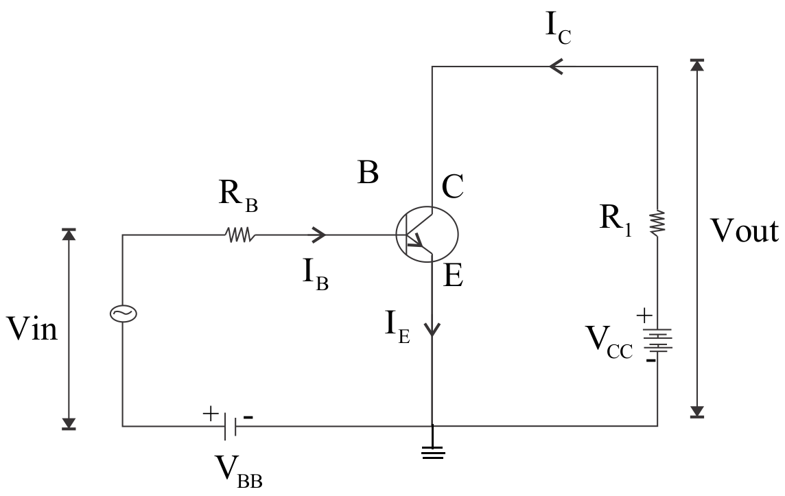
The input signal to be amplified is applied across the input circuit (base-emitter circuit). The input circuit is forward biased using a battery of e.m.f. ${V_{BB}}$ volt. The amplified output signal is taken across the load resistance in the output circuit (collector-emitter circuit). The output circuit is reverse biased using a battery of e.m.f. ${V_{CC}}$ volt. According to Kirchhoff’s junction law, emitter current (${I_E}$), base current (${I_B}$), collector current (${I_C}$) are related as
${I_E} = {I_B} + {I_C}$ -(i)
When current (${I_C}$) flows through the load resistance (${R_L}$), the output or collector voltage is given by, ${V_0} = $ applied voltage ${V_{CC}} - $ voltage-drop across ${R_L}$.
i.e. ${V_0} = {V_{CE}} = {V_{CC}} - {R_L}{I_C}$ -(ii)
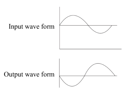
During a positive half cycle of input signal, the forward bias of emitter-base junction increases. Due to increased forward bias, emitter current (${I_E}$) increases and hence according to eqn. (i), collector current (${I_C}$) also increases. Therefore, the voltage-drop across ${R_L}$ (${R_L}$${I_C}$) increases. According to eqn. (ii), the collector voltage or output voltage (${V_0}$) decreases. Since the collector is connected to the positive terminal of the battery (${V_{CC}}$) so decrease in ${V_0}$means that the collector voltage becomes less positive. In other words, an amplified negative signal is obtained across the output.
Similarly, during the negative half cycle of input signal, the forward bias of emitter-base junction decreases. Due to this, emitter current (${I_E}$) decreases and collector current (${I_C}$) also decreases. Therefore, the voltage-drop across ${R_L}$ (${R_L}$${I_C}$) also decreases. Hence according to eqn. (ii), the collector voltage or output voltage (${V_0}$) increases. Since the collector is connected to the positive terminal of the battery (${V_{CC}}$) so an increase in ${V_0}$means that the collector voltage becomes more positive. In other words, an amplified positive signal is obtained across the output.
Note: Since, the output voltage decreases with increasing input signal and increases with decreasing input signal, so the both input and output signals are out of phase. In other words, there is a phase difference of $\pi $ or 180o between input and output.
Complete step by step answer:
The input signal to be amplified is applied across the input circuit (base-emitter circuit). The input circuit is forward biased using a battery of e.m.f. ${V_{BB}}$ volt. The amplified output signal is taken across the load resistance in the output circuit (collector-emitter circuit). The output circuit is reverse biased using a battery of e.m.f. ${V_{CC}}$ volt. According to Kirchhoff’s junction law, emitter current (${I_E}$), base current (${I_B}$), collector current (${I_C}$) are related as
${I_E} = {I_B} + {I_C}$ -(i)
When current (${I_C}$) flows through the load resistance (${R_L}$), the output or collector voltage is given by, ${V_0} = $ applied voltage ${V_{CC}} - $ voltage-drop across ${R_L}$.
i.e. ${V_0} = {V_{CE}} = {V_{CC}} - {R_L}{I_C}$ -(ii)
During a positive half cycle of input signal, the forward bias of emitter-base junction increases. Due to increased forward bias, emitter current (${I_E}$) increases and hence according to eqn. (i), collector current (${I_C}$) also increases. Therefore, the voltage-drop across ${R_L}$ (${R_L}$${I_C}$) increases. According to eqn. (ii), the collector voltage or output voltage (${V_0}$) decreases. Since the collector is connected to the positive terminal of the battery (${V_{CC}}$) so decrease in ${V_0}$means that the collector voltage becomes less positive. In other words, an amplified negative signal is obtained across the output.
Similarly, during the negative half cycle of input signal, the forward bias of emitter-base junction decreases. Due to this, emitter current (${I_E}$) decreases and collector current (${I_C}$) also decreases. Therefore, the voltage-drop across ${R_L}$ (${R_L}$${I_C}$) also decreases. Hence according to eqn. (ii), the collector voltage or output voltage (${V_0}$) increases. Since the collector is connected to the positive terminal of the battery (${V_{CC}}$) so an increase in ${V_0}$means that the collector voltage becomes more positive. In other words, an amplified positive signal is obtained across the output.
Note: Since, the output voltage decreases with increasing input signal and increases with decreasing input signal, so the both input and output signals are out of phase. In other words, there is a phase difference of $\pi $ or 180o between input and output.
Recently Updated Pages
Basicity of sulphurous acid and sulphuric acid are
Master Class 12 Economics: Engaging Questions & Answers for Success
Master Class 12 Biology: Engaging Questions & Answers for Success
Master Class 11 English: Engaging Questions & Answers for Success
Master Class 11 Physics: Engaging Questions & Answers for Success
Master Class 11 Computer Science: Engaging Questions & Answers for Success
Trending doubts
Draw a labelled sketch of the human eye class 12 physics CBSE
The chemical formula of tear gas is A CO Cl 2 B C 10 class 12 chemistry CBSE
Draw ray diagrams each showing i myopic eye and ii class 12 physics CBSE
Which are the Top 10 Largest Countries of the World?
Differentiate between homogeneous and heterogeneous class 12 chemistry CBSE
Which is the correct genotypic ratio of mendel dihybrid class 12 biology CBSE