


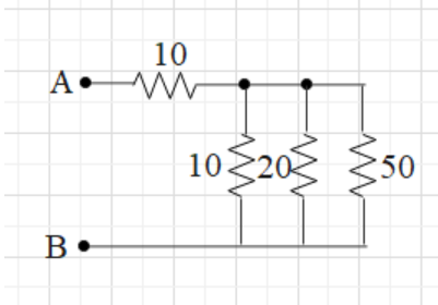
The resistance between A and B in the given figure will be(in ohm):
A.20
B.30
C.90
D. more than 10 but less than 20
Answer
597.6k+ views
Hint: In the given circuit different resistors are connected between terminal A and B. We will use the formula for resistance in series and parallel combinations. First, we solve for the resistors connected in parallel to make the circuit simple. After calculating we will get resultant resistance and then it will be in series.
Formula used: In parallel \[\dfrac{1}{R}=\dfrac{1}{{{R}_{1}}}+\dfrac{1}{{{R}_{2}}}+......\]
In series \[R={{R}_{1}}+{{R}_{2}}+....\]
Complete step-by-step solution:
In the given figure it is clear that some of the resistors are in series and some in parallel. In the given circuit let us suppose \[r=10\Omega ,{{r}_{1}}=10\Omega \], \[{{r}_{2}}=20\Omega \] and \[{{r}_{3}}=50\Omega \].
Now we can see that \[{{r}_{1}}\],\[{{r}_{2}}\] and \[{{r}_{3}}\] are connected in parallel. Therefore the formula for calculating resistors connected parallel is \[\dfrac{1}{R}=\dfrac{1}{{{R}_{1}}}+\dfrac{1}{{{R}_{2}}}+......\]
\[\begin{align}
& \dfrac{1}{{{r}_{e}}}=\dfrac{1}{{{r}_{1}}}+\dfrac{1}{{{r}_{2}}}+\dfrac{1}{{{r}_{3}}} \\
& =\dfrac{1}{10}+\dfrac{1}{20}+\dfrac{1}{50} \\
& =\dfrac{17}{100} \\
\end{align}\]
\[\Rightarrow {{r}_{e}}=\dfrac{100}{17}\Omega \]
As we got \[{{r}_{e}}=\dfrac{100}{17}\Omega \] , so\[r\] and \[{{r}_{e}}\] will be in series combination.
Equivalent resistance in the will be
\[\begin{align}
&\Rightarrow R=r+{{r}_{e}} \\
&\Rightarrow R=10+\dfrac{100}{17}=\dfrac{270}{17}=15.88\Omega \\
\end{align}\]
Thus the total resistance is found to be \[15.88\Omega \] which is more than \[10\Omega \] and less than \[20\Omega \]. So option D is correct.
Additional information: Resistance, the name itself suggests it resists the current flowing through it. It is the property of the conductor. Resistance is the ratio of voltage and current in the current. The resistor has two terminals. Useful components like capacitors are added with resistors to resist the flow of current in the circuit. It is used to protect the other components in the circuit.
Note: In a circuit, there are different resistors connected in series and parallel combination. In series combination, the current through each resistor is the same while in parallel combination the potential through each resistor is the same.
Recently Updated Pages
Master Class 12 Social Science: Engaging Questions & Answers for Success
Master Class 12 Physics: Engaging Questions & Answers for Success
Master Class 12 Maths: Engaging Questions & Answers for Success
Master Class 12 Economics: Engaging Questions & Answers for Success
Master Class 12 Chemistry: Engaging Questions & Answers for Success
Master Class 12 Business Studies: Engaging Questions & Answers for Success
Trending doubts
Which are the Top 10 Largest Countries of the World?
Draw a labelled sketch of the human eye class 12 physics CBSE
Explain the structure of megasporangium class 12 biology CBSE
What are the major means of transport Explain each class 12 social science CBSE
How many chromosomes are found in human ovum a 46 b class 12 biology CBSE
The diagram of the section of a maize grain is given class 12 biology CBSE