


The outputs of two NOT gates are fed to a NOR gate. Draw the logic circuit of the combination of gates. Give its truth table. Identify the gate represented by this combination.
Answer
630.3k+ views
Hint: Use the properties of combination of logic gates.
Complete step by step solution:
Logic gates
• In digital electronics, we consider only two values of voltage – high represented as 1 and law represented as O.
• Logic gates are electronic circuits.
• Just as gates control the flow of vehicles, logic gates control the flow of information based on the logical relations. Only if the logical relations are satisfied, the digital circuit allows the signal to pass through.
• The logic gates are basic building blocks of digital electronics.
• We can say a logic gate is a digital circuit which follows a logical relationship between the input and output.
• Some of the basic types of logic gates are– NOT, OR, AND, NOR and NAND. Every gate has a single or multiple input and output.
•Every gate is represented by a symbol.
• The input and output of logic gates is represented in the form of a truth table.
• The truth table considers all possible combinations of the input and shows respective output in each case.
Note Gate
The symbol and truth table for NOT gate is given below
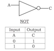
Single input
Single output
\[C\,\,=\,\,\overline{A}\]
NOR gate: The symbol and truth table for NOT gate is as given below.
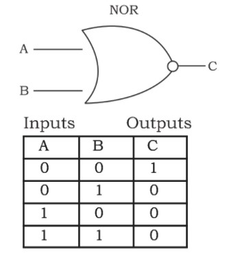
Two inputs
Single output
\[C\,\,=\,\,\overline{A+B}\]
AND gate
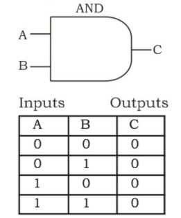
Two inputs
Single outputs
C = A.B
According to the given question
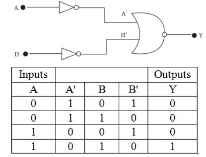
Identification: AND gate.
Note: (1) NOT gate has single input and single output
(2) NOR gate has two inputs and single output
(3) AND gate has two inputs and single output
Complete step by step solution:
Logic gates
• In digital electronics, we consider only two values of voltage – high represented as 1 and law represented as O.
• Logic gates are electronic circuits.
• Just as gates control the flow of vehicles, logic gates control the flow of information based on the logical relations. Only if the logical relations are satisfied, the digital circuit allows the signal to pass through.
• The logic gates are basic building blocks of digital electronics.
• We can say a logic gate is a digital circuit which follows a logical relationship between the input and output.
• Some of the basic types of logic gates are– NOT, OR, AND, NOR and NAND. Every gate has a single or multiple input and output.
•Every gate is represented by a symbol.
• The input and output of logic gates is represented in the form of a truth table.
• The truth table considers all possible combinations of the input and shows respective output in each case.
Note Gate
The symbol and truth table for NOT gate is given below
Single input
Single output
\[C\,\,=\,\,\overline{A}\]
NOR gate: The symbol and truth table for NOT gate is as given below.
Two inputs
Single output
\[C\,\,=\,\,\overline{A+B}\]
AND gate
Two inputs
Single outputs
C = A.B
According to the given question
Identification: AND gate.
Note: (1) NOT gate has single input and single output
(2) NOR gate has two inputs and single output
(3) AND gate has two inputs and single output
Recently Updated Pages
Master Class 11 English: Engaging Questions & Answers for Success
Master Class 11 Social Science: Engaging Questions & Answers for Success
Master Class 11 Maths: Engaging Questions & Answers for Success
Master Class 11 Biology: Engaging Questions & Answers for Success
Master Class 11 Physics: Engaging Questions & Answers for Success
Master Class 11 Chemistry: Engaging Questions & Answers for Success
Trending doubts
One Metric ton is equal to kg A 10000 B 1000 C 100 class 11 physics CBSE
Difference Between Prokaryotic Cells and Eukaryotic Cells
Find the value of the expression given below sin 30circ class 11 maths CBSE
Difference between physical and chemical change class 11 chemistry CBSE
Two of the body parts which do not appear in MRI are class 11 biology CBSE
Draw a diagram of a plant cell and label at least eight class 11 biology CBSE