


The given circuit has two ideal diodes connected as shown in the figure below. The current flowing through the resistance ${{R}_{1}}$ will be:
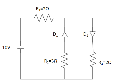
A. 3.13A
B. 2.5A
C. 10.0A
D. 1.43A
Answer
596.1k+ views
Hint: Knowledge of forward and reverse bias conditions for a pn junction diode is required. Given, since the diodes are ideal, hence the resistance of the diode will be zero in forward biasing condition and infinity in reverse biasing condition. Further, Ohm’s law would also be required to find the current value: $V=IR\Rightarrow I=\dfrac{V}{R}$.
Complete step-by-step answer:
Let’s remake the circuit, by putting in the signs of the potential of the battery connected, the currents flowing through different arms of the circuit.
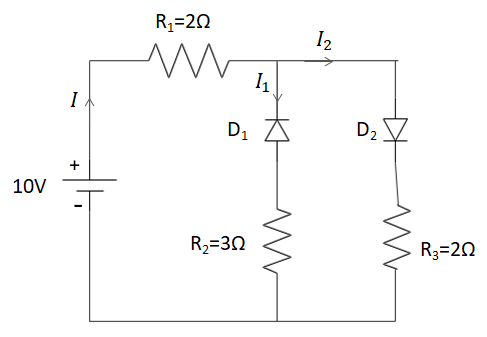
To understand the division of the current flowing through the circuit, we will use the Kirchoff’s current law. Hence, considering the amount of current to be flowing through the resistance${{R}_{1}}$to be I. Then, the circuit breaks into two arms. Hence, the current also gets divided into \[{{I}_{1}}\]and ${{I}_{2}}$.
Hence, the sum of \[{{I}_{1}}\]and ${{I}_{2}}$will be I.
We will now discuss the diodes. A pn junction diode is a semiconductor containing excess electrons and holes on each end of the diode and a P-N junction (or) interface in between. A common region is formed in between the P and the N side having equal amounts of holes and electrons.
The P-side of the pn junction diode refers to the positive side of the semiconductor diode having holes in excess and similarly, the N-side of the pn junction diode refers to the negative side of the semiconductor diode having electrons in excess.
In this case the diode \[{{D}_{1}}\]is connected in the reverse bias condition and the diode \[{{D}_{2}}\]is connected in the forward bias condition. Further given in the question, we have both of these diodes to be ideal diodes. Hence, under the reverse bias condition, the resistance offered by the diode is infinity. Similarly the resistance offered by the diode in a forward bias condition is zero.
Taking this into account, there wouldn’t be any current flowing through the diode\[{{D}_{1}}\]. Therefore, ${{I}_{1}}=0$.
Hence, $I={{I}_{1}}+{{I}_{2}}\Rightarrow I={{I}_{2}}$. Therefore, the value of current flowing in the circuit can be found using the Ohm’s law: $V=IR
\Rightarrow 10V=I{{R}_{net}}
\Rightarrow 10V=I({{R}_{1}}+{{R}_{2}})
\Rightarrow 10V=I(4\Omega )
\Rightarrow I=2.5A$.
Hence, the amount of current flowing through the resistance ${{R}_{1}}$ is 2.5A.
Note: We consider the value of the net resistance in the above condition to be: ${{R}_{net}}={{R}_{1}}+{{R}_{2}}$because, the resistances are in series to each other. The net resistance of the circuit, when the resistances are connected in series is given by the sum of the resistance values of the resistors connected.
Complete step-by-step answer:
Let’s remake the circuit, by putting in the signs of the potential of the battery connected, the currents flowing through different arms of the circuit.
To understand the division of the current flowing through the circuit, we will use the Kirchoff’s current law. Hence, considering the amount of current to be flowing through the resistance${{R}_{1}}$to be I. Then, the circuit breaks into two arms. Hence, the current also gets divided into \[{{I}_{1}}\]and ${{I}_{2}}$.
Hence, the sum of \[{{I}_{1}}\]and ${{I}_{2}}$will be I.
We will now discuss the diodes. A pn junction diode is a semiconductor containing excess electrons and holes on each end of the diode and a P-N junction (or) interface in between. A common region is formed in between the P and the N side having equal amounts of holes and electrons.
The P-side of the pn junction diode refers to the positive side of the semiconductor diode having holes in excess and similarly, the N-side of the pn junction diode refers to the negative side of the semiconductor diode having electrons in excess.
In this case the diode \[{{D}_{1}}\]is connected in the reverse bias condition and the diode \[{{D}_{2}}\]is connected in the forward bias condition. Further given in the question, we have both of these diodes to be ideal diodes. Hence, under the reverse bias condition, the resistance offered by the diode is infinity. Similarly the resistance offered by the diode in a forward bias condition is zero.
Taking this into account, there wouldn’t be any current flowing through the diode\[{{D}_{1}}\]. Therefore, ${{I}_{1}}=0$.
Hence, $I={{I}_{1}}+{{I}_{2}}\Rightarrow I={{I}_{2}}$. Therefore, the value of current flowing in the circuit can be found using the Ohm’s law: $V=IR
\Rightarrow 10V=I{{R}_{net}}
\Rightarrow 10V=I({{R}_{1}}+{{R}_{2}})
\Rightarrow 10V=I(4\Omega )
\Rightarrow I=2.5A$.
Hence, the amount of current flowing through the resistance ${{R}_{1}}$ is 2.5A.
Note: We consider the value of the net resistance in the above condition to be: ${{R}_{net}}={{R}_{1}}+{{R}_{2}}$because, the resistances are in series to each other. The net resistance of the circuit, when the resistances are connected in series is given by the sum of the resistance values of the resistors connected.
Recently Updated Pages
Master Class 12 Economics: Engaging Questions & Answers for Success
Master Class 12 Physics: Engaging Questions & Answers for Success
Master Class 12 English: Engaging Questions & Answers for Success
Master Class 12 Social Science: Engaging Questions & Answers for Success
Master Class 12 Maths: Engaging Questions & Answers for Success
Master Class 12 Business Studies: Engaging Questions & Answers for Success
Trending doubts
Which are the Top 10 Largest Countries of the World?
What are the major means of transport Explain each class 12 social science CBSE
Draw a labelled sketch of the human eye class 12 physics CBSE
Differentiate between insitu conservation and exsitu class 12 biology CBSE
Draw a neat and well labeled diagram of TS of ovary class 12 biology CBSE
Give 10 examples of unisexual and bisexual flowers