


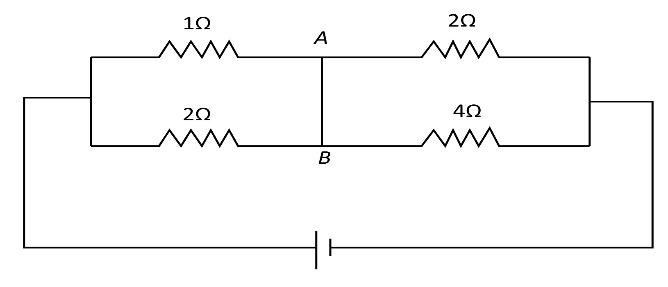
The current flowing through the segment $AB$ of the circuit shown in figure is
(A) $1\;{\rm{amp}}$ from $A$ to $B$
(B) $1\;{\rm{amp}}$ from $B$ to $A$
(C) $2\;{\rm{amp}}$ from $A$ to $B$
(D) $2\;{\rm{amp}}$ from $B$ to $A$
Answer
584.7k+ views
Hint: First, we can redraw the circuit diagram so that it is easy to identify the parallel resistances and the resistances in series with each other. We can apply the current divider rule to the circuit to find the solution.
Complete step by step answer:Let us first redraw the given circuit diagram as follows:
Here the points $A$ and $B$ are joined using a metal wire. Hence, the potential difference across the points $A$ and $B$ is zero. Thus
Let us define ${R_1} = 1\;\Omega $, ${R_2} = 3\;\Omega $, ${R_3} = 2\;\Omega $ and ${R_4} = 4\;\Omega $. From the circuit diagram, the resistances ${R_1}$ and ${R_2}$ are connected parallel to each other. Similarly, the resistances ${R_3}$ and ${R_4}$ are connected parallel to each other.
The equivalent resistance of the resistances ${R_1}$ and ${R_2}$ can be written as
${R_{1,2}} = \dfrac{{{R_1}{R_2}}}{{{R_1} + {R_2}}}$
Here ${R_{1,2}}$ is the equivalent resistance of the resistances ${R_1}$ and ${R_2}$.
Substituting the values for ${R_1}$ and ${R_2}$ in the above equation, we get
\begin{align*}
{R_{1,2}} &= \dfrac{{1\;\Omega \times 3\;\Omega }}{{1\;\Omega + 3\;\Omega }}\\
\Rightarrow {R_{1,2}} &= \dfrac{3}{4}\;\Omega
\end{align*}
Again, we can write the equation for the equivalent resistance of the resistances ${R_3}$ and ${R_4}$ as
${R_{3,4}} = \dfrac{{{R_3}{R_4}}}{{{R_3} + {R_4}}}$
Here ${R_{3,4}}$ is the equivalent resistance of the resistances ${R_3}$ and ${R_4}$.
Substituting the values for ${R_3}$ and ${R_4}$ in the above equation, we get
\begin{align*}
{R_{3,4}} &= \dfrac{{2\;\Omega \times 4\;\Omega }}{{2\;\Omega + 4\;\Omega }}\\
\Rightarrow {R_{3,4}} &= \dfrac{{8\;{\Omega ^2}}}{{6\;\Omega }}\\
\Rightarrow {R_{3,4}} &= \dfrac{4}{3}\;\Omega
\end{align*}
From the circuit diagram we can see that the combination of parallel resistances ${R_1}$ and ${R_2}$ is in series with the combination of parallel resistances ${R_3}$ and ${R_4}$. Hence, we can write the equation for the equivalent resistance of the four resistances as,
$R = {R_{1,2}} + {R_{3,4}}$
Here $R$ is the equivalent resistance of the four resistances.
Now, we can substitute $\dfrac{3}{4}\;\Omega $ for ${R_{1,2}}$ and $\dfrac{4}{3}\;\Omega $ for ${R_{3,4}}$ in the above equation to get,
\begin{align*}
R &= \dfrac{3}{4}\;\Omega + \dfrac{4}{3}\;\Omega \\
\Rightarrow R &= \left( {\dfrac{{3 \times 3 + 4 \times 4}}{{4 \times 3}}} \right)\;\Omega \\
\Rightarrow R &= \dfrac{{25}}{{12}}\;\;\Omega
\end{align*}
Now the total current flowing through the circuit can be written as
$I = \dfrac{V}{R}$
Here $V$ is the voltage across the circuit.
Since $V = 25\;{\rm{V}}$ and $R = \dfrac{{25}}{{12}}\;\Omega $, we can substitute the values for $R$ and $V$ to get the total current. Hence,
\begin{align*}
I &= \dfrac{{25\;{\rm{V}}}}{{\dfrac{{25}}{{12}}\;\Omega }}\\
\Rightarrow I &= 12\;{\rm{A}}
\end{align*}
Now, using the current divider rule, we can write the equation for the current ${I_1}$ flowing between point $P$ to $A$ as,
${I_1} = \dfrac{{{R_2}}}{{{R_1} + {R_2}}}I$
Substituting the values for ${R_1}$, ${R_2}$ and $I$ in the above equation, we get
\begin{align*}
{I_1} &= \dfrac{{3\;\Omega }}{{1\;\Omega + 3\;\Omega }} \times 12\;{\rm{A}}\\
\Rightarrow {I_1} &= \dfrac{3}{4} \times 12\;{\rm{A}}\\
\Rightarrow {I_1} &= 9\;{\rm{A}}
\end{align*}
Again, using the current divider rule, we can write equation for the current ${I_3}$ flowing from point $B$ to $Q$ as,
${I_3} = \dfrac{{{R_3}}}{{{R_3} + {R_4}}}I$
Substituting the values for ${R_3}$, ${R_4}$ and $I$ in the above equation, we get
\begin{align*}
{I_3} &= \dfrac{{4\;\Omega }}{{2\;\Omega + 4\;\Omega }} \times 12\,{\rm{A}}\\
\Rightarrow {I_3} &= \dfrac{4}{6} \times 12\,{\rm{A}}\\
\Rightarrow {I_3} &= 8\;{\rm{A}}
\end{align*}
Now, the current flowing through the segment $AB$ can be written as
$i = {I_1} - {I_3}$
Here $i$ is the current flowing through the segment $AB$.
Now substituting the values of ${I_1}$ and ${I_3}$, we get
\begin{align*}
i &= 9\;{\rm{A - 8}}\;{\rm{A}}\\
\Rightarrow i &= 1\;{\rm{A}}
\end{align*}
Since, the current obtained has a positive value, we can confirm that the direction of the current is from $A$ to $B$.
Therefore, the option (A) is correct.
Note:It should be noted that the resistances connected between two pints at the same potential difference are in parallel. Similarly, we should also note that the resistances connected between points at different potential differences are in series.
Recently Updated Pages
Master Class 12 Social Science: Engaging Questions & Answers for Success
Master Class 12 Physics: Engaging Questions & Answers for Success
Master Class 12 Maths: Engaging Questions & Answers for Success
Master Class 12 Economics: Engaging Questions & Answers for Success
Master Class 12 Chemistry: Engaging Questions & Answers for Success
Master Class 12 Business Studies: Engaging Questions & Answers for Success
Trending doubts
Which are the Top 10 Largest Countries of the World?
Draw a labelled sketch of the human eye class 12 physics CBSE
Explain the structure of megasporangium class 12 biology CBSE
What are the major means of transport Explain each class 12 social science CBSE
How many chromosomes are found in human ovum a 46 b class 12 biology CBSE
The diagram of the section of a maize grain is given class 12 biology CBSE