


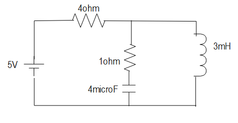
in the figure, the steady state current through the inductor will be:
Answer
612.6k+ views
Hint: In this question we will directly use the Ohm’s law, which gives the relation between the current, voltage and resistance. Further, by substituting the given values, we will get the required result. Also, we will discuss the basics of an electrical circuit for better understanding.
Formula used:
$I = \dfrac{V}{R}$
Complete answer:
As we know, during steady state, the inductor acts as a closed circuit, whereas the capacitor acts as an open circuit.
Also, as we know that according to the ohm’s law on constant temperature the current I pass through the conductor is directly proportional to the potential difference V across its ends.
$\eqalign{& I \propto V \cr
& I = \dfrac{V}{R} \cr} $
Substituting the value of voltage and resistance in the above equation, we get:
$\eqalign{& I = \dfrac{5}{4} \cr
& \therefore I = 1.25A \cr} $
Therefore, we get the required result for the steady state current in the given inductor, which is given by the above result.
Additional information:
We should know that in a series circuit, the output current of the first resistor flows into the input of the second resistor; so, the current is the same in each resistor whereas In a parallel circuit, all of the resistor are on connected together on one side and all the leads on the other side are connected together.
In a circuit if the resistance is constant over a range of voltage, then I = V/R, can be used to predict the behavior of the material. This involves DC current and voltage, it is the same for the resistors. Further, a material obeys Ohm's law or does not obey; the resistance of the material can be described in terms of its bulk. The resistivity, and the resistance both, is temperature dependent. Over certain ranges of temperature, this temperature dependence can be predicted from resistance.
Note:
There are limitations to Ohm's law. They are valid only for conductors not for all materials. We should also note that resistance is inversely proportional to the flow of current. The unit of resistance is ohm, named after the scientist. Internal resistance of a circuit refers to the opposition to the flow of current offered by the cells and batteries themselves thereby, resulting in the generation of heat.
Recently Updated Pages
Master Class 11 English: Engaging Questions & Answers for Success
Master Class 11 Social Science: Engaging Questions & Answers for Success
Master Class 11 Maths: Engaging Questions & Answers for Success
Master Class 11 Biology: Engaging Questions & Answers for Success
Master Class 11 Physics: Engaging Questions & Answers for Success
Master Class 11 Chemistry: Engaging Questions & Answers for Success
Trending doubts
One Metric ton is equal to kg A 10000 B 1000 C 100 class 11 physics CBSE
Difference Between Prokaryotic Cells and Eukaryotic Cells
Find the value of the expression given below sin 30circ class 11 maths CBSE
Difference between physical and chemical change class 11 chemistry CBSE
Two of the body parts which do not appear in MRI are class 11 biology CBSE
Draw a diagram of a plant cell and label at least eight class 11 biology CBSE