


In an electrical circuit, $ R $ , $ L $ , $ C $ and ac voltage source are all connected in series. When $ L $ is removed from the circuit, the phase difference between the voltage and the current in the circuit is $ \dfrac{\pi }{3} $ . If instead $ C $ is removed from the circuit, the phase difference is again $ \dfrac{\pi }{3} $ . The power factor of the circuit is
(A) $ \dfrac{1}{2} $
(B) $ \dfrac{1}{{\sqrt 2 }} $
(C) $ 1 $
(D) $ \dfrac{{\sqrt 3 }}{2} $
Answer
575.1k+ views
Hint: To solve this question, we need to consider the phase diagram for a series $ R $ , $ L $ , $ C $ circuit to get the relation between the phase difference and the inductive reactance, capacitive reactance, and the resistance. Substituting the values of the phase difference for the two cases, we will get the values for the inductive and the capacitive reactances. On substituting these in the derived relation, we will get the value of the phase difference, and hence the value of the power factor.
Complete step-by-step solution
In the given question, we have been given a series $ R $ , $ L $ , $ C $ circuit.
Considering the phase difference of a series $ R $ , $ L $ , $ C $ circuit, we have the following figure.
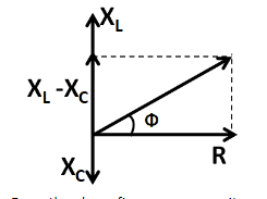
From the above figure, we can write
$ \tan \phi = \dfrac{{\left| {{X_L} - {X_C}} \right|}}{R} $ .........................(1)
According to the question, we have been given two cases. In the first case when the inductance is removed, the phase difference is equal to $ \dfrac{\pi }{3} $ . When the inductance is removed, then the inductive reactance will become zero. So the above information can be written as
$ {\phi _1} = \dfrac{\pi }{3} $ , and
$ {X_L} = 0 $
Substituting these in (1) we get
$ \tan \left( {\dfrac{\pi }{3}} \right) = \dfrac{{\left| {0 - {X_C}} \right|}}{R} $
$ \Rightarrow \sqrt 3 = \dfrac{{{X_C}}}{R} $
Multiplying by $ R $ both the sides, we get
$ {X_C} = \sqrt 3 R $ .........................(2)
Now, in the second case when the capacitance is removed, then also the phase difference is equal to $ \dfrac{\pi }{3} $ when the capacitance is removed, then the capacitive reactance will become zero. So the above information can be written as
$ {\phi _2} = \dfrac{\pi }{3} $ , and
$ {X_C} = 0 $
Substituting these in (1) we get
$ \tan \left( {\dfrac{\pi }{3}} \right) = \dfrac{{\left| {{X_L} - 0} \right|}}{R} $
$ \Rightarrow \sqrt 3 = \dfrac{{{X_L}}}{R} $
Multiplying by $ R $ both the sides, we get
$ {X_L} = \sqrt 3 R $ .........................(3)
Now, we substitute (2) and (3) in (1) to get the phase difference between the voltage and current in the given circuit as
$ \tan \phi = \dfrac{{\left| {\sqrt 3 R - \sqrt 3 R} \right|}}{R} $
$ \Rightarrow \tan \phi = 0 $
Taking tangent inverse both the sides, we get
$ \phi = 0 $
Now, we know that the power factor of a series $ R $ , $ L $ , $ C $ circuit is equal to the cosine of the phase difference between the voltage and the current. That is,
$ PF = \cos \phi $
$ \Rightarrow PF = \cos 0 = 1 $
Thus, the power factor of the given circuit is equal to $ 1 $ .
Hence, the correct answer is option C.
Note
There is no need to use the expressions for the inductive and the capacitive reactances in terms of the frequency while using the expression for the phase difference. That will only make things more complicated.
Complete step-by-step solution
In the given question, we have been given a series $ R $ , $ L $ , $ C $ circuit.
Considering the phase difference of a series $ R $ , $ L $ , $ C $ circuit, we have the following figure.
From the above figure, we can write
$ \tan \phi = \dfrac{{\left| {{X_L} - {X_C}} \right|}}{R} $ .........................(1)
According to the question, we have been given two cases. In the first case when the inductance is removed, the phase difference is equal to $ \dfrac{\pi }{3} $ . When the inductance is removed, then the inductive reactance will become zero. So the above information can be written as
$ {\phi _1} = \dfrac{\pi }{3} $ , and
$ {X_L} = 0 $
Substituting these in (1) we get
$ \tan \left( {\dfrac{\pi }{3}} \right) = \dfrac{{\left| {0 - {X_C}} \right|}}{R} $
$ \Rightarrow \sqrt 3 = \dfrac{{{X_C}}}{R} $
Multiplying by $ R $ both the sides, we get
$ {X_C} = \sqrt 3 R $ .........................(2)
Now, in the second case when the capacitance is removed, then also the phase difference is equal to $ \dfrac{\pi }{3} $ when the capacitance is removed, then the capacitive reactance will become zero. So the above information can be written as
$ {\phi _2} = \dfrac{\pi }{3} $ , and
$ {X_C} = 0 $
Substituting these in (1) we get
$ \tan \left( {\dfrac{\pi }{3}} \right) = \dfrac{{\left| {{X_L} - 0} \right|}}{R} $
$ \Rightarrow \sqrt 3 = \dfrac{{{X_L}}}{R} $
Multiplying by $ R $ both the sides, we get
$ {X_L} = \sqrt 3 R $ .........................(3)
Now, we substitute (2) and (3) in (1) to get the phase difference between the voltage and current in the given circuit as
$ \tan \phi = \dfrac{{\left| {\sqrt 3 R - \sqrt 3 R} \right|}}{R} $
$ \Rightarrow \tan \phi = 0 $
Taking tangent inverse both the sides, we get
$ \phi = 0 $
Now, we know that the power factor of a series $ R $ , $ L $ , $ C $ circuit is equal to the cosine of the phase difference between the voltage and the current. That is,
$ PF = \cos \phi $
$ \Rightarrow PF = \cos 0 = 1 $
Thus, the power factor of the given circuit is equal to $ 1 $ .
Hence, the correct answer is option C.
Note
There is no need to use the expressions for the inductive and the capacitive reactances in terms of the frequency while using the expression for the phase difference. That will only make things more complicated.
Recently Updated Pages
Master Class 12 Social Science: Engaging Questions & Answers for Success
Master Class 12 Physics: Engaging Questions & Answers for Success
Master Class 12 Maths: Engaging Questions & Answers for Success
Master Class 12 Economics: Engaging Questions & Answers for Success
Master Class 12 Chemistry: Engaging Questions & Answers for Success
Master Class 12 Business Studies: Engaging Questions & Answers for Success
Trending doubts
Which are the Top 10 Largest Countries of the World?
Draw a labelled sketch of the human eye class 12 physics CBSE
Explain the structure of megasporangium class 12 biology CBSE
What are the major means of transport Explain each class 12 social science CBSE
How many chromosomes are found in human ovum a 46 b class 12 biology CBSE
The diagram of the section of a maize grain is given class 12 biology CBSE