


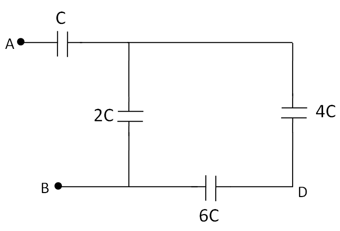
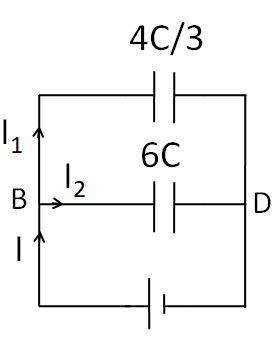
If $C = 50\mu F$in the figure below,
What is the equivalent capacitance between points A and B?
Repeat for points A and D.
Answer
581.7k+ views
Hint
To solve this question, we need to imagine a battery across the points where the equivalent capacitance is required. Then, identifying the series and parallel combinations, apply the suitable formulae for the equivalent capacitance.
The formulae used in this solution are
$\Rightarrow \dfrac{1}{{{C_s}}} = \dfrac{1}{{{C_1}}} + \dfrac{1}{{{C_2}}} + ...........$
$\Rightarrow {C_p} = {C_1} + {C_2} + ...........$
Where ${C_s}$ is the equivalent series capacitance, and ${C_p}$ is the equivalent parallel capacitance of the capacitances ${C_1}$,${C_2}$……..
Complete step by step answer
(A) We first imagine that a battery is connected between the point A and B, as shown in the figure below.
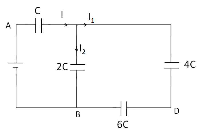
According to the current distribution in the figure, we can see that the same current ${I_1}$ is flowing through $4C$ and $6C$ capacitances. So these two capacitances are in series.
So the equivalent capacitance of $4C$ and $6C$ capacitances is given as
$\Rightarrow \dfrac{1}{{{C_s}}} = \dfrac{1}{{4C}} + \dfrac{1}{{6C}}$
Taking the LCM, we get
$\Rightarrow \dfrac{1}{{{C_s}}} = \dfrac{{3 + 2}}{{12C}}$
Taking reciprocal, we have
$\Rightarrow {C_s} = \dfrac{{12C}}{5}$
Now, the above circuit is reduced to

As the capacitances $2C$ and $\dfrac{{12C}}{5}$ are end to end connected, so they form a parallel combination. The equivalent capacitance of $2C$and $\dfrac{{12C}}{5}$ capacitances is given by
$\Rightarrow {C_p} = 2C + \dfrac{{12C}}{5}$
$\Rightarrow {C_p} = \dfrac{{22C}}{5}$
Now, the above circuit reduces to
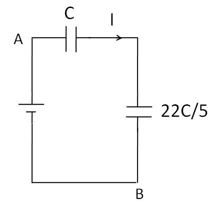
As the same current $I$is flowing through $C$and $\dfrac{{22C}}{5}$capacitances. So these two capacitances are in series. So the equivalent capacitance of $C$and $\Rightarrow \dfrac{{22C}}{5}$capacitances is given as
$\Rightarrow \dfrac{1}{{{C_s}}} = \dfrac{1}{C} + \dfrac{1}{{\dfrac{{22C}}{5}}}$
$\Rightarrow \dfrac{1}{{{C_s}}} = \dfrac{1}{C} + \dfrac{5}{{22C}}$
Taking the LCM, we get
$\Rightarrow \dfrac{1}{{{C_s}}} = \dfrac{{27}}{{22C}}$
Taking reciprocal
$\Rightarrow {C_s} = \dfrac{{22C}}{{27}}$
As only this capacitance is left, this is the equivalent capacitance between the points A and B. Substituting $C = 50\mu F$
$\Rightarrow {C_s} = \dfrac{{22}}{{27}} \times 50 = 40.74 \mu F$
(B) Now, we imagine a battery between points B and D, as shown in the figure below.

As the left end of the capacitance $C$is not connected to any point, no current will flow through it, so it can be taken out of the circuit. Thus, the circuit reduces to
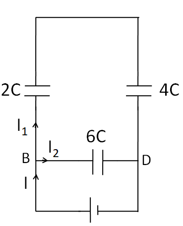
As the same current ${I_1}$ is flowing through $4C$ and $2C$ capacitances. So these two capacitances are in series.
So the equivalent capacitance of $4C$ and $2C$ capacitances is given as
$\Rightarrow \dfrac{1}{{{C_s}}} = \dfrac{1}{{4C}} + \dfrac{1}{{2C}}$
Taking the LCM, we get
$\Rightarrow \dfrac{1}{{{C_s}}} = \dfrac{3}{{4C}}$
Taking reciprocal, we have
$\Rightarrow {C_s} = \dfrac{{4C}}{3}$
Now, the above circuit is reduced to
As the capacitances $6C$ and $\dfrac{{4C}}{3}$ are end to end connected, so they form a parallel combination. The equivalent capacitance of $6C$ and $\dfrac{{4C}}{3}$ capacitances is given by
$\Rightarrow {C_p} = 6C + \dfrac{{4C}}{3}$
$\Rightarrow {C_p} = \dfrac{{22C}}{3}$
As only this capacitance is left, so this is the equivalent capacitance between the points B and D.
Substituting $C = 50\mu F$
$\Rightarrow {C_s} = \dfrac{{22}}{3} \times 50 = 366.67\mu F$
Hence, the equivalent capacitance between the points A and B is $40.74\mu F$ and between the points B and D is $366.67\mu F$.
Note
The current distributions shown in the diagrams after connecting a virtual battery are just for identifying the combinations of capacitances. They do not have any theoretical significance. As we all know, that under a DC source, a capacitor behaves as an open circuit, so the current in the circuit would be zero. The current distributions although not being theoretically correct, help us in identifying the series and parallel combinations of capacitances, just like we do in the case of resistances.
To solve this question, we need to imagine a battery across the points where the equivalent capacitance is required. Then, identifying the series and parallel combinations, apply the suitable formulae for the equivalent capacitance.
The formulae used in this solution are
$\Rightarrow \dfrac{1}{{{C_s}}} = \dfrac{1}{{{C_1}}} + \dfrac{1}{{{C_2}}} + ...........$
$\Rightarrow {C_p} = {C_1} + {C_2} + ...........$
Where ${C_s}$ is the equivalent series capacitance, and ${C_p}$ is the equivalent parallel capacitance of the capacitances ${C_1}$,${C_2}$……..
Complete step by step answer
(A) We first imagine that a battery is connected between the point A and B, as shown in the figure below.
According to the current distribution in the figure, we can see that the same current ${I_1}$ is flowing through $4C$ and $6C$ capacitances. So these two capacitances are in series.
So the equivalent capacitance of $4C$ and $6C$ capacitances is given as
$\Rightarrow \dfrac{1}{{{C_s}}} = \dfrac{1}{{4C}} + \dfrac{1}{{6C}}$
Taking the LCM, we get
$\Rightarrow \dfrac{1}{{{C_s}}} = \dfrac{{3 + 2}}{{12C}}$
Taking reciprocal, we have
$\Rightarrow {C_s} = \dfrac{{12C}}{5}$
Now, the above circuit is reduced to
As the capacitances $2C$ and $\dfrac{{12C}}{5}$ are end to end connected, so they form a parallel combination. The equivalent capacitance of $2C$and $\dfrac{{12C}}{5}$ capacitances is given by
$\Rightarrow {C_p} = 2C + \dfrac{{12C}}{5}$
$\Rightarrow {C_p} = \dfrac{{22C}}{5}$
Now, the above circuit reduces to
As the same current $I$is flowing through $C$and $\dfrac{{22C}}{5}$capacitances. So these two capacitances are in series. So the equivalent capacitance of $C$and $\Rightarrow \dfrac{{22C}}{5}$capacitances is given as
$\Rightarrow \dfrac{1}{{{C_s}}} = \dfrac{1}{C} + \dfrac{1}{{\dfrac{{22C}}{5}}}$
$\Rightarrow \dfrac{1}{{{C_s}}} = \dfrac{1}{C} + \dfrac{5}{{22C}}$
Taking the LCM, we get
$\Rightarrow \dfrac{1}{{{C_s}}} = \dfrac{{27}}{{22C}}$
Taking reciprocal
$\Rightarrow {C_s} = \dfrac{{22C}}{{27}}$
As only this capacitance is left, this is the equivalent capacitance between the points A and B. Substituting $C = 50\mu F$
$\Rightarrow {C_s} = \dfrac{{22}}{{27}} \times 50 = 40.74 \mu F$
(B) Now, we imagine a battery between points B and D, as shown in the figure below.
As the left end of the capacitance $C$is not connected to any point, no current will flow through it, so it can be taken out of the circuit. Thus, the circuit reduces to
As the same current ${I_1}$ is flowing through $4C$ and $2C$ capacitances. So these two capacitances are in series.
So the equivalent capacitance of $4C$ and $2C$ capacitances is given as
$\Rightarrow \dfrac{1}{{{C_s}}} = \dfrac{1}{{4C}} + \dfrac{1}{{2C}}$
Taking the LCM, we get
$\Rightarrow \dfrac{1}{{{C_s}}} = \dfrac{3}{{4C}}$
Taking reciprocal, we have
$\Rightarrow {C_s} = \dfrac{{4C}}{3}$
Now, the above circuit is reduced to
As the capacitances $6C$ and $\dfrac{{4C}}{3}$ are end to end connected, so they form a parallel combination. The equivalent capacitance of $6C$ and $\dfrac{{4C}}{3}$ capacitances is given by
$\Rightarrow {C_p} = 6C + \dfrac{{4C}}{3}$
$\Rightarrow {C_p} = \dfrac{{22C}}{3}$
As only this capacitance is left, so this is the equivalent capacitance between the points B and D.
Substituting $C = 50\mu F$
$\Rightarrow {C_s} = \dfrac{{22}}{3} \times 50 = 366.67\mu F$
Hence, the equivalent capacitance between the points A and B is $40.74\mu F$ and between the points B and D is $366.67\mu F$.
Note
The current distributions shown in the diagrams after connecting a virtual battery are just for identifying the combinations of capacitances. They do not have any theoretical significance. As we all know, that under a DC source, a capacitor behaves as an open circuit, so the current in the circuit would be zero. The current distributions although not being theoretically correct, help us in identifying the series and parallel combinations of capacitances, just like we do in the case of resistances.
Recently Updated Pages
Master Class 12 Economics: Engaging Questions & Answers for Success
Master Class 12 Physics: Engaging Questions & Answers for Success
Master Class 12 English: Engaging Questions & Answers for Success
Master Class 12 Social Science: Engaging Questions & Answers for Success
Master Class 12 Maths: Engaging Questions & Answers for Success
Master Class 12 Business Studies: Engaging Questions & Answers for Success
Trending doubts
Which are the Top 10 Largest Countries of the World?
What are the major means of transport Explain each class 12 social science CBSE
Draw a labelled sketch of the human eye class 12 physics CBSE
Differentiate between insitu conservation and exsitu class 12 biology CBSE
Draw a neat and well labeled diagram of TS of ovary class 12 biology CBSE
Give 10 examples of unisexual and bisexual flowers