


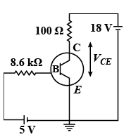
For the transistor circuit shown in figure, if \[\beta = 100\], voltage drop across emitter and base is 0.7V, then the value of \[{V_{CE}}\] will be
Answer
627.9k+ views
Hint: Use KVL in the first loop to determine the base current. We know the amplification factor is the ratio of collector current to base current. Calculate the collector current using the given amplification factor. Then use KVL in the second loop to express the voltage drop across collector and emitter.
Formula used:
According to Ohm’s law,
\[V = IR\]
\[{\beta _{AC}} = \dfrac{{{I_C}}}{{{I_B}}}\]
Here, \[{I_C}\] is the collector current and \[{\beta _{AC}}\] s the AC current gain.
Complete step by step answer:
We can find the base current in the above transistor circuit by applying KVL in the first loop containing 5V supply, \[8\,k\Omega \] resistance as follows,
\[5 - 8.6{I_B} - {V_{BE}} = 0\]
Here, \[{V_{BE}}\] is the voltage drop across base and emitter and \[{I_B}\] is the base current.
We substitute 0.7 V for \[{V_{BE}}\] in the above equation.
\[5 - 8.6{I_B} - 0.7 = 0\]
\[ \Rightarrow {I_B} = \dfrac{{5 - 0.7}}{{8.6}}\]
\[ \Rightarrow {I_B} = 0.5\,mA\]
We know the relation,
\[{\beta _{AC}} = \dfrac{{{I_C}}}{{{I_B}}}\]
\[ \Rightarrow {I_C} = {\beta _{AC}}{I_B}\]
Here, \[{I_C}\] is the collector current and \[{\beta _{AC}}\] s the AC current gain.
We substitute 100 for \[{\beta _{AC}}\] and 0.5 mA for \[{I_B}\] in the above equation.
\[{I_C} = \left( {100} \right)\left( {0.5\,mA} \right)\]
\[ \Rightarrow {I_C} = 50\,mA\]
Now, to determine the voltage drop across collector-emitter, we apply KVL is the second loop as follows,
\[{V_{CC}} - {I_C}R - {V_{CE}} = 0\]
Here, \[{V_{CC}}\] is the collector voltage and \[{V_{CE}}\] is the voltage across the collector-emitter.
We substitute 18 V for \[{V_{CC}}\], 50mA for \[{I_C}\] and \[100\,\Omega \] for R in the above equation.
\[18 - \left( {50 \times {{10}^{ - 3}}\,A} \right)\left( {100\,\Omega } \right) - {V_{CE}} = 0\]
\[ \Rightarrow {V_{CE}} = 13\,V\]
Therefore, the voltage drop across the collector-emitter is 13 V.
Note:
We know KVL states that the voltage in the complete loop is the sum of voltage drop across each component. IF there is addition of voltage in the loop, then it should be taken as positive and if there is drop in the voltage then it should be taken as negative. In the above solution, we have taken the collector voltage positive because it gets added in the voltage from the second loop.
Recently Updated Pages
Basicity of sulphurous acid and sulphuric acid are
Master Class 12 Economics: Engaging Questions & Answers for Success
Master Class 12 Biology: Engaging Questions & Answers for Success
Master Class 11 English: Engaging Questions & Answers for Success
Master Class 11 Physics: Engaging Questions & Answers for Success
Master Class 11 Computer Science: Engaging Questions & Answers for Success
Trending doubts
Draw a labelled sketch of the human eye class 12 physics CBSE
The chemical formula of tear gas is A CO Cl 2 B C 10 class 12 chemistry CBSE
Draw ray diagrams each showing i myopic eye and ii class 12 physics CBSE
Which are the Top 10 Largest Countries of the World?
Differentiate between homogeneous and heterogeneous class 12 chemistry CBSE
Which is the correct genotypic ratio of mendel dihybrid class 12 biology CBSE