


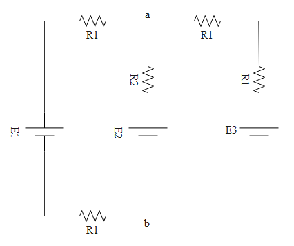
For the circuit shown, with ${R_1}$=1.0Ω, ${R_2}$=2.0Ω, ${E_1}$=2 V and ${E_2} = {E_3}$=4 V, the potential difference between the points ′a′ and ′b′ is approximately (in V).
Answer
609.6k+ views
Hint: In order to find out the effective resistance we use series and parallel connection formulas. Similarly cells also can be connected in series and parallel. If cells are connected in series we have one formula to find the effective emf and if cells are connected in parallel we have another formula to find effective emf.
Formula used:
$\eqalign{
& {R_s} = {R_1} + {R_2} + {R_3} + ......... \cr
& \dfrac{1}{{{R_P}}} = \dfrac{1}{{{R_1}}} + \dfrac{1}{{{R_2}}} + \dfrac{1}{{{R_3}}} + ....... \cr} $
${E_{eff}} = \dfrac{{\dfrac{{{E_X}}}{{{R_X}}} + \dfrac{{{E_Y}}}{{{R_Y}}} + \dfrac{{{E_Z}}}{{{R_Z}}}}}{{\dfrac{1}{{{R_X}}} + \dfrac{1}{{{R_Y}}} + \dfrac{1}{{{R_Z}}}}}$
Complete answer:
Rate of flow of charge is known as current. A material which allows current to pass through it is known as a conductor. No conductor will be perfect. It will have some resistance. The property to hinder the flow of current is called resistance and a device which does that is known as a resistor.
If the same current is passing through all resistors then we tell those are connected in series. If potential difference is the same for all resistors then those resistors are told to be in parallel.
The circuit is given below
When resistors are connected in series then effective resistance is ${R_s} = {R_1} + {R_2} + {R_3} + .........$
When resistors are connected in parallel effective resistance will be $\dfrac{1}{{{R_P}}} = \dfrac{1}{{{R_1}}} + \dfrac{1}{{{R_2}}} + \dfrac{1}{{{R_3}}} + .......$

If we clearly observe the above circuit, in the right side loop, both ${R_1}$ resistors are in series.
So the effective resistance will be
$\eqalign{
& {R_s} = {R_1} + {R_2} + {R_3} + ......... \cr
& \Rightarrow {R_s} = {R_1} + {R_1} \cr
& \Rightarrow {R_s} = 2{R_1} \cr} $
In the left side loop too, both ${R_1}$ resistors are in series.
So the effective resistance will be
$\eqalign{
& {R_s} = {R_1} + {R_2} + {R_3} + ......... \cr
& \Rightarrow {R_s} = {R_1} + {R_1} \cr
& \Rightarrow {R_s} = 2{R_1} \cr} $
Now $2{R_1}$ can be considered as resistance adjacent to ${E_1}$ and ${R_2}$ can be considered as resistance adjacent to ${E_2}$ and $2{R_1}$ can be considered as resistance adjacent to ${E_3}$. The effective circuit is shown below.
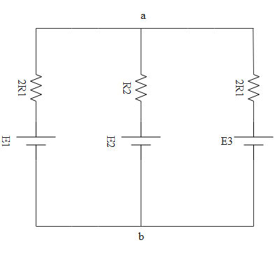
So all 3 cells are in parallel with polarities at one side, no cell is reversed. So the effective emf will be
${E_{eff}} = \dfrac{{\dfrac{{{E_X}}}{{{R_X}}} + \dfrac{{{E_Y}}}{{{R_Y}}} + \dfrac{{{E_Z}}}{{{R_Z}}}}}{{\dfrac{1}{{{R_X}}} + \dfrac{1}{{{R_Y}}} + \dfrac{1}{{{R_Z}}}}}$
Where resistors ${R_X}$, ${R_Y}$, ${R_Z}$ are in parallel condition too. They are adjacent to respective resistors.
$\eqalign{
& {E_{eff}} = \dfrac{{\dfrac{{{E_1}}}{{2{R_1}}} + \dfrac{{{E_2}}}{{{R_2}}} + \dfrac{{{E_3}}}{{2{R_1}}}}}{{\dfrac{1}{{2{R_1}}} + \dfrac{1}{{{R_2}}} + \dfrac{1}{{2{R_1}}}}} \cr
& \Rightarrow {E_{eff}} = \dfrac{{\dfrac{2}{2} + \dfrac{4}{2} + \dfrac{4}{2}}}{{\dfrac{1}{2} + \dfrac{1}{2} + \dfrac{1}{2}}} \cr
& \Rightarrow {E_{eff}} = \dfrac{{10}}{3} \cr
& \Rightarrow {E_{eff}} = 3.3V \cr} $
Hence the potential difference across terminals a and b will be 3.3 volts
Note:
The parallel effective emf formula which we had applied was actually derived for the case to find effective emf when cells with internal emf’s are connected in parallel. Here also we can use the same formula by considering the resistances adjacent to cells as the internal resistances.
Formula used:
$\eqalign{
& {R_s} = {R_1} + {R_2} + {R_3} + ......... \cr
& \dfrac{1}{{{R_P}}} = \dfrac{1}{{{R_1}}} + \dfrac{1}{{{R_2}}} + \dfrac{1}{{{R_3}}} + ....... \cr} $
${E_{eff}} = \dfrac{{\dfrac{{{E_X}}}{{{R_X}}} + \dfrac{{{E_Y}}}{{{R_Y}}} + \dfrac{{{E_Z}}}{{{R_Z}}}}}{{\dfrac{1}{{{R_X}}} + \dfrac{1}{{{R_Y}}} + \dfrac{1}{{{R_Z}}}}}$
Complete answer:
Rate of flow of charge is known as current. A material which allows current to pass through it is known as a conductor. No conductor will be perfect. It will have some resistance. The property to hinder the flow of current is called resistance and a device which does that is known as a resistor.
If the same current is passing through all resistors then we tell those are connected in series. If potential difference is the same for all resistors then those resistors are told to be in parallel.
The circuit is given below
When resistors are connected in series then effective resistance is ${R_s} = {R_1} + {R_2} + {R_3} + .........$
When resistors are connected in parallel effective resistance will be $\dfrac{1}{{{R_P}}} = \dfrac{1}{{{R_1}}} + \dfrac{1}{{{R_2}}} + \dfrac{1}{{{R_3}}} + .......$
If we clearly observe the above circuit, in the right side loop, both ${R_1}$ resistors are in series.
So the effective resistance will be
$\eqalign{
& {R_s} = {R_1} + {R_2} + {R_3} + ......... \cr
& \Rightarrow {R_s} = {R_1} + {R_1} \cr
& \Rightarrow {R_s} = 2{R_1} \cr} $
In the left side loop too, both ${R_1}$ resistors are in series.
So the effective resistance will be
$\eqalign{
& {R_s} = {R_1} + {R_2} + {R_3} + ......... \cr
& \Rightarrow {R_s} = {R_1} + {R_1} \cr
& \Rightarrow {R_s} = 2{R_1} \cr} $
Now $2{R_1}$ can be considered as resistance adjacent to ${E_1}$ and ${R_2}$ can be considered as resistance adjacent to ${E_2}$ and $2{R_1}$ can be considered as resistance adjacent to ${E_3}$. The effective circuit is shown below.
So all 3 cells are in parallel with polarities at one side, no cell is reversed. So the effective emf will be
${E_{eff}} = \dfrac{{\dfrac{{{E_X}}}{{{R_X}}} + \dfrac{{{E_Y}}}{{{R_Y}}} + \dfrac{{{E_Z}}}{{{R_Z}}}}}{{\dfrac{1}{{{R_X}}} + \dfrac{1}{{{R_Y}}} + \dfrac{1}{{{R_Z}}}}}$
Where resistors ${R_X}$, ${R_Y}$, ${R_Z}$ are in parallel condition too. They are adjacent to respective resistors.
$\eqalign{
& {E_{eff}} = \dfrac{{\dfrac{{{E_1}}}{{2{R_1}}} + \dfrac{{{E_2}}}{{{R_2}}} + \dfrac{{{E_3}}}{{2{R_1}}}}}{{\dfrac{1}{{2{R_1}}} + \dfrac{1}{{{R_2}}} + \dfrac{1}{{2{R_1}}}}} \cr
& \Rightarrow {E_{eff}} = \dfrac{{\dfrac{2}{2} + \dfrac{4}{2} + \dfrac{4}{2}}}{{\dfrac{1}{2} + \dfrac{1}{2} + \dfrac{1}{2}}} \cr
& \Rightarrow {E_{eff}} = \dfrac{{10}}{3} \cr
& \Rightarrow {E_{eff}} = 3.3V \cr} $
Hence the potential difference across terminals a and b will be 3.3 volts
Note:
The parallel effective emf formula which we had applied was actually derived for the case to find effective emf when cells with internal emf’s are connected in parallel. Here also we can use the same formula by considering the resistances adjacent to cells as the internal resistances.
Recently Updated Pages
Master Class 11 English: Engaging Questions & Answers for Success
Master Class 11 Social Science: Engaging Questions & Answers for Success
Master Class 11 Maths: Engaging Questions & Answers for Success
Master Class 11 Biology: Engaging Questions & Answers for Success
Master Class 11 Physics: Engaging Questions & Answers for Success
Master Class 11 Chemistry: Engaging Questions & Answers for Success
Trending doubts
One Metric ton is equal to kg A 10000 B 1000 C 100 class 11 physics CBSE
Difference Between Prokaryotic Cells and Eukaryotic Cells
Find the value of the expression given below sin 30circ class 11 maths CBSE
Difference between physical and chemical change class 11 chemistry CBSE
Two of the body parts which do not appear in MRI are class 11 biology CBSE
Draw a diagram of a plant cell and label at least eight class 11 biology CBSE