


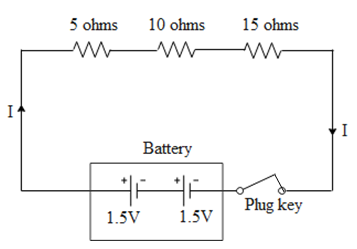
Draw the schematic diagram of an electric schematic diagram of an electric circuit consisting of a battery of two cells of 1.5 V each, three resistances of 5 ohm, 10 ohm and 15 ohm respectively and a plug key all connected in series.
Answer
616.2k+ views
Hint: It is given in the question that all the components of the circuit are connected in series. Hence, while drawing the circuit diagram all the components should be connected one after the other. The direction of the current is to be taken from the positive to the negative terminal of the battery.
Complete step by step answer:
Given below is a circuit diagram consisting of three resistances in series, connected across a battery. The net resistance in the circuit is 30 ohms. Let us assume that the internal resistance of each cell is negligible. Therefore we can conclude that the net emf of the battery is 3 volts. As soon as the key is plugged in the current will flow in the circuit. By ohm's law i.e. $V=IR$ (where V is the net emf of the battery, I is the current in the circuit and R is the net resistance in series)current in the circuit is 0.1 amperes.
Note:
In the above circuit diagram, both the cells in the battery are connected in the same direction. If the batteries are connected in the opposite direction than, than the net emf in the circuit will be zero. Hence from ohms law we can conclude that the current in the circuit will be zero as the net emf of the battery is zero.
Recently Updated Pages
Master Class 11 Social Science: Engaging Questions & Answers for Success
Master Class 11 English: Engaging Questions & Answers for Success
Master Class 11 Maths: Engaging Questions & Answers for Success
Master Class 11 Chemistry: Engaging Questions & Answers for Success
Master Class 11 Biology: Engaging Questions & Answers for Success
Master Class 11 Physics: Engaging Questions & Answers for Success
Trending doubts
Differentiate between an exothermic and an endothermic class 11 chemistry CBSE
One Metric ton is equal to kg A 10000 B 1000 C 100 class 11 physics CBSE
Difference Between Prokaryotic Cells and Eukaryotic Cells
There are 720 permutations of the digits 1 2 3 4 5 class 11 maths CBSE
Draw a diagram of a plant cell and label at least eight class 11 biology CBSE
Which chemical is known as king of chemicals A H 2 class 11 chemistry CBSE