


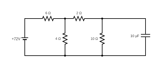
Determine the charge on the capacitor in the given circuit:
A. $2 \mu F$
B. $60 \mu F$
C. $200 \mu F$
D. $10 \mu F$
Answer
610.2k+ views
Hint: To solve this problem, first find the equivalent resistance of the circuit loop-by-loop. Using this obtained equivalent resistance and voltage of the cell, obtain the value of initial current. Then, use the current to find the potential difference across the $6\Omega$ resistor. After flowing through the $6\Omega$ resistor the current gets divided into ${I}_{1}$ and ${I}_{2}$. Find values of ${I}_{1}$ and ${I}_{2}$ using the initial current. Then, find the potential difference across $4\Omega$. Use the relationship between charge, potential difference and capacitance. Substitute the value of potential difference across ${R}_{4}$ resistor and capacitance to find the charge on the capacitor. This will give the charge on the capacitor in the given circuit.
Formula used:
$ \dfrac {1}{{R}_{eq}}= \dfrac {1} {{R}_{1}} + \dfrac {1}{{R}_{2}}+ \dfrac {1}{{R}_{3}}+ …+\dfrac {1}{{R}_{N}}$
$V= IR$
$Q= CV$
Complete answer:
Given: ${R}_{1}= 6 \Omega$
${R}_{2}= 4 \Omega$
${R}_{3}= 2 \Omega$
${R}_{4}= 10 \Omega$
$V= 72 V$
$C = 10 \mu F$
Equivalent resistance is given by,
$ \dfrac {1}{{R}_{eq}}= \dfrac {1} {{R}_{1}} + \dfrac {1}{{R}_{2}}+ \dfrac {1}{{R}_{3}}+ …+\dfrac {1}{{R}_{N}}$
Resistors ${R}_{3}$ and ${R}_{4}$ are in series. So, the equivalent resistance will be,
${R}_{eq}= {R}_{3} + {R}_{4}$
Substituting the values in above equation we get,
${R}_{eq}= 2 + 10$
$\Rightarrow {R}_{eq}= 12 \Omega$
So, now we can draw the above circuit as given below,
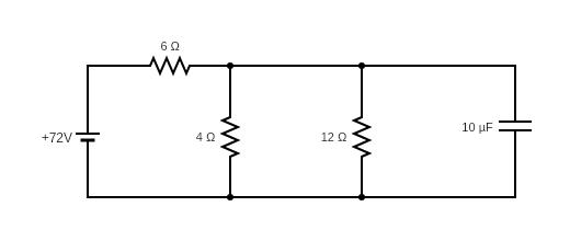
Now, in the above circuit, we can see ${R}_{eq}$ and ${R}_{2}$ are in parallel. So, we can write the equivalent resistance as,
$\dfrac {1}{{{R}_{eq}}_{1}}= \dfrac {1}{{R}_{eq}} + \dfrac {1}{{R}_{2}}$
Substituting the values in above equation we get,
$\dfrac {1}{{{R}_{eq}}_{1}}= \dfrac {1}{12} + \dfrac {1}{4}$
$\Rightarrow \dfrac {1}{{{R}_{eq}}_{1}}=\dfrac {4}{12}$
${{R}_{eq}}_{1}= 3 \Omega$
This ${{R}_{eq}}_{1}$ is in series with ${R}_{1}$. So. the equivalent resistance of the circuit becomes,
${{R}_{eq}}_{2}= {{R}_{eq}}_{1} + {R}_{1}$
Substituting the values in above equation we get,
${{R}_{eq}}_{2}= 6 + 3$
$\Rightarrow {{R}_{eq}}_{2}=9 \Omega$
According to Ohm’s law,
$V= IR$
Substituting the values in above equation we get,
$72 = I \times 9$
$\Rightarrow I = 8 A$
Potential difference across $6 \Omega $ resistor is given by,
${V}_{0}= V – IR$
Substituting the values we get,
${V}_{0}= 72 – (8 \times 6)$
$\Rightarrow {V}_{0}= 72-48$
$\Rightarrow {V}_{0}= 24 V$
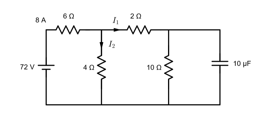
From, the figure above, we can infer that,
$8= {I}_{1}+{I}_{2}$ …(1)
${I}_{1}= \dfrac {8 \times 4}{ 12 + 4}$
$\Rightarrow {I}_{1}= \dfrac {32}{16}$
$\Rightarrow {I}_{1}= 2 A$
Substituting above value in equation. (1) we get,
$8= 2 + {I}_{2}$
$\Rightarrow {I}_{2}= 6 A$
Potential drop across ${R}_{4}$ resistor is given by,
${V}_{1}= {I}_{1} \times {R}_{4}$
Substituting the values in above equation we get,
${V}_{1}= 2 \times 10$
$\Rightarrow {V}_{1}= 20 V$
We know, relationship between charge and capacitance is given by,
$Q= CV$
$\Rightarrow Q= C {V}_{1}$
Substituting the values in above equation we get,
$Q= 10 \times {10}^{-6} \times 20$
$\Rightarrow Q = 200 \times {10}^{-6}$
$\Rightarrow Q= 200 \mu F$
Hence, the charge on the capacitor is $200 \mu F$.
So, the correct answer is “Option C”.
Note:
Students must take care while applying series and parallel formulas for calculating the resistances. Students should remember that the equivalent resistance of a combination is always less than the smallest resistance in the parallel network. As we add more resistors in the network, the total resistance of the circuit will always decrease. While, in a series network, the equivalent resistance of the network is greater than the value of the largest resistor in the chain. The current flowing through each parallel branch may not be the same. But the voltage across each resistor in a parallel network is always the same.
Formula used:
$ \dfrac {1}{{R}_{eq}}= \dfrac {1} {{R}_{1}} + \dfrac {1}{{R}_{2}}+ \dfrac {1}{{R}_{3}}+ …+\dfrac {1}{{R}_{N}}$
$V= IR$
$Q= CV$
Complete answer:
Given: ${R}_{1}= 6 \Omega$
${R}_{2}= 4 \Omega$
${R}_{3}= 2 \Omega$
${R}_{4}= 10 \Omega$
$V= 72 V$
$C = 10 \mu F$
Equivalent resistance is given by,
$ \dfrac {1}{{R}_{eq}}= \dfrac {1} {{R}_{1}} + \dfrac {1}{{R}_{2}}+ \dfrac {1}{{R}_{3}}+ …+\dfrac {1}{{R}_{N}}$
Resistors ${R}_{3}$ and ${R}_{4}$ are in series. So, the equivalent resistance will be,
${R}_{eq}= {R}_{3} + {R}_{4}$
Substituting the values in above equation we get,
${R}_{eq}= 2 + 10$
$\Rightarrow {R}_{eq}= 12 \Omega$
So, now we can draw the above circuit as given below,
Now, in the above circuit, we can see ${R}_{eq}$ and ${R}_{2}$ are in parallel. So, we can write the equivalent resistance as,
$\dfrac {1}{{{R}_{eq}}_{1}}= \dfrac {1}{{R}_{eq}} + \dfrac {1}{{R}_{2}}$
Substituting the values in above equation we get,
$\dfrac {1}{{{R}_{eq}}_{1}}= \dfrac {1}{12} + \dfrac {1}{4}$
$\Rightarrow \dfrac {1}{{{R}_{eq}}_{1}}=\dfrac {4}{12}$
${{R}_{eq}}_{1}= 3 \Omega$
This ${{R}_{eq}}_{1}$ is in series with ${R}_{1}$. So. the equivalent resistance of the circuit becomes,
${{R}_{eq}}_{2}= {{R}_{eq}}_{1} + {R}_{1}$
Substituting the values in above equation we get,
${{R}_{eq}}_{2}= 6 + 3$
$\Rightarrow {{R}_{eq}}_{2}=9 \Omega$
According to Ohm’s law,
$V= IR$
Substituting the values in above equation we get,
$72 = I \times 9$
$\Rightarrow I = 8 A$
Potential difference across $6 \Omega $ resistor is given by,
${V}_{0}= V – IR$
Substituting the values we get,
${V}_{0}= 72 – (8 \times 6)$
$\Rightarrow {V}_{0}= 72-48$
$\Rightarrow {V}_{0}= 24 V$
From, the figure above, we can infer that,
$8= {I}_{1}+{I}_{2}$ …(1)
${I}_{1}= \dfrac {8 \times 4}{ 12 + 4}$
$\Rightarrow {I}_{1}= \dfrac {32}{16}$
$\Rightarrow {I}_{1}= 2 A$
Substituting above value in equation. (1) we get,
$8= 2 + {I}_{2}$
$\Rightarrow {I}_{2}= 6 A$
Potential drop across ${R}_{4}$ resistor is given by,
${V}_{1}= {I}_{1} \times {R}_{4}$
Substituting the values in above equation we get,
${V}_{1}= 2 \times 10$
$\Rightarrow {V}_{1}= 20 V$
We know, relationship between charge and capacitance is given by,
$Q= CV$
$\Rightarrow Q= C {V}_{1}$
Substituting the values in above equation we get,
$Q= 10 \times {10}^{-6} \times 20$
$\Rightarrow Q = 200 \times {10}^{-6}$
$\Rightarrow Q= 200 \mu F$
Hence, the charge on the capacitor is $200 \mu F$.
So, the correct answer is “Option C”.
Note:
Students must take care while applying series and parallel formulas for calculating the resistances. Students should remember that the equivalent resistance of a combination is always less than the smallest resistance in the parallel network. As we add more resistors in the network, the total resistance of the circuit will always decrease. While, in a series network, the equivalent resistance of the network is greater than the value of the largest resistor in the chain. The current flowing through each parallel branch may not be the same. But the voltage across each resistor in a parallel network is always the same.
Recently Updated Pages
Master Class 9 General Knowledge: Engaging Questions & Answers for Success
Master Class 9 Maths: Engaging Questions & Answers for Success
Master Class 9 Science: Engaging Questions & Answers for Success
Master Class 9 English: Engaging Questions & Answers for Success
Master Class 9 Social Science: Engaging Questions & Answers for Success
Class 9 Question and Answer - Your Ultimate Solutions Guide
Trending doubts
Which are the Top 10 Largest Countries of the World?
Draw a labelled sketch of the human eye class 12 physics CBSE
Differentiate between homogeneous and heterogeneous class 12 chemistry CBSE
Sulphuric acid is known as the king of acids State class 12 chemistry CBSE
Why is the cell called the structural and functional class 12 biology CBSE
A dentist uses a small mirror that gives a magnification class 12 physics CBSE