


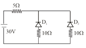
Calculate the current through the given circuit (the diodes are ideal)
(A) 6A
(B) 12A
(C) 1As
(D) 2A
Answer
586.8k+ views
Hint: For solving the circuit diagram first we use the biasing of diode i.e. if the diode is reversed biased then there is no current flow in the circuit. If the diode is forward biased then there is current flow in the circuit. If resistance are in series then total resistance is ${R_1} + {R_2} + ....$. After then applying ohm’s law we will get the value of current flowing in the circuit.
Complete step by step answer:
In the circuit diagram, we can sec ${D_1}$ is reversed biased that means there are no current flow through ${D_1}$
${D_2}$ is forward biased that means there are current flow through ${D_2}$
So the total resistance of the circuit is
${R_L} + {R_{{D_2}}}$
$\Rightarrow{T_{total}} = 5 + 10$
$\Rightarrow{R_{total}} = 15\Omega $
We know according to ohm’s law current through the circuit
$I = \dfrac{v}{r}$
Given that $v = 30\,V$
${R_{total}} = 15\Omega $
So, $I = \dfrac{{30}}{{15}}$
$\therefore I = 2\,A$
Hence option D is correct.
Note: Forward biasing means p part of p-n junction diode is connected to $ + ve$ terminal of battery and $ - ve$ terminal to n junction. Reverse biasing means p terminal is connected to $ - ve$ terminal and n junction is connected to $ + ve$ terminal of battery
Recently Updated Pages
Master Class 12 Business Studies: Engaging Questions & Answers for Success
Master Class 12 Chemistry: Engaging Questions & Answers for Success
Master Class 12 Biology: Engaging Questions & Answers for Success
Class 12 Question and Answer - Your Ultimate Solutions Guide
Master Class 11 English: Engaging Questions & Answers for Success
Master Class 11 Social Science: Engaging Questions & Answers for Success
Trending doubts
Which are the Top 10 Largest Countries of the World?
Draw a labelled sketch of the human eye class 12 physics CBSE
Differentiate between homogeneous and heterogeneous class 12 chemistry CBSE
In order to find out the different types of gametes class 12 biology NEET_UG
Why is the cell called the structural and functional class 12 biology CBSE
Draw ray diagrams each showing i myopic eye and ii class 12 physics CBSE