


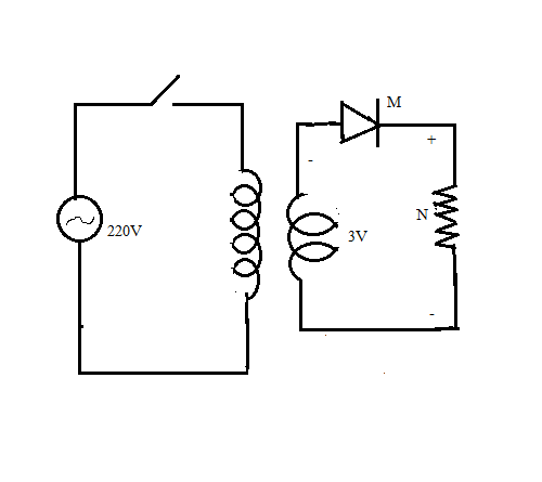
Analyse the given circuit diagram of a half wave rectifier and answer the following questions.
a. Identify the components labelled as M and N.
b. What are the changes to be made in the following components for the converting this to a full wave rectifier
i. Transformer
ii. No. of Diodes
iii. Draw the output form of a full rectifier.
Answer
600.9k+ views
Hint: In a half wave rectifier there always remains a diode, a load resistance, a transformer and an A.C input. Again, for a full wave rectifier, there are two diodes instead of one and there is a load resistance, a transformer and an A.C input.
Complete step-by-step answer:
a) The component labelled as M is a diode and the diode in a half wave rectifier is forward biased. The component labelled N is a load resistance. As the diode M is forward biased, it allows the flow of current through the circuit.
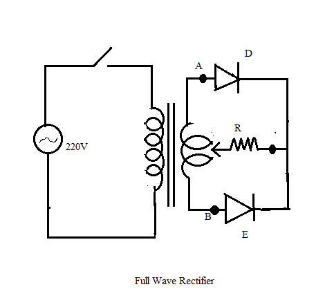
b) For the half wave rectifier to be changed to a full wave rectifier, the change in the given components should be as follows-
i. In case of a full wave rectifier, the transformer should be a centre-tap transformer.
ii. There are two diodes in case of a full wave rectifier, one of the diodes is forward biased and the other is reverse biased.
The output form of a full wave rectifier is given below,
Note: Students must be very careful about the fact that in a full wave rectifier, one of the diodes is reverse biased and the other is forward biased. As a result, current flows only through one diode, that is through the diode which is forward biased. They must also pay attention towards the use of a centre-tap transformer in case of a full-wave rectifier.
Complete step-by-step answer:
a) The component labelled as M is a diode and the diode in a half wave rectifier is forward biased. The component labelled N is a load resistance. As the diode M is forward biased, it allows the flow of current through the circuit.
b) For the half wave rectifier to be changed to a full wave rectifier, the change in the given components should be as follows-
i. In case of a full wave rectifier, the transformer should be a centre-tap transformer.
ii. There are two diodes in case of a full wave rectifier, one of the diodes is forward biased and the other is reverse biased.
The output form of a full wave rectifier is given below,
Note: Students must be very careful about the fact that in a full wave rectifier, one of the diodes is reverse biased and the other is forward biased. As a result, current flows only through one diode, that is through the diode which is forward biased. They must also pay attention towards the use of a centre-tap transformer in case of a full-wave rectifier.
Recently Updated Pages
Master Class 12 Business Studies: Engaging Questions & Answers for Success
Master Class 12 Biology: Engaging Questions & Answers for Success
Master Class 12 Chemistry: Engaging Questions & Answers for Success
Class 12 Question and Answer - Your Ultimate Solutions Guide
Complete reduction of benzene diazonium chloride with class 12 chemistry CBSE
How can you identify optical isomers class 12 chemistry CBSE
Trending doubts
Which are the Top 10 Largest Countries of the World?
What are the major means of transport Explain each class 12 social science CBSE
Draw a labelled sketch of the human eye class 12 physics CBSE
Differentiate between insitu conservation and exsitu class 12 biology CBSE
Draw a neat and well labeled diagram of TS of ovary class 12 biology CBSE
Differentiate between homogeneous and heterogeneous class 12 chemistry CBSE