


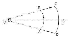
An infinite current-carrying wire passes through point O and is perpendicular to the plane containing the current-carrying loop ABCD as shown in the figure. Choose the correct options:
The question has multiple correct options
a) net force on the loop is zero
b) net torque on the loop is zero
c) As seen from O, the loop rotates clockwise
d) As seen from O, the loop rotates anticlockwise
Answer
600.6k+ views
Hint: A current-carrying wire passes through the point O as shown in the above figure. Hence it will generate a magnetic field in the region surrounding it such that it has a constant value along the circumference of a circle of given radius r from its center. Hence we will calculate the force on each section of the loop due to the magnetic field of the wire through O and see which statement is valid from the given options.
Complete step by step answer:
To begin with, let us analyze the force on each section of the loop.
Before that let us understand the concept right-hand rule for two vectors perpendicular to each other
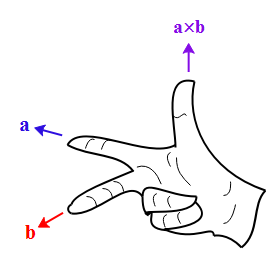
If we see the above diagram, if there are two vectors a and b represented by the middle and the forefinger of your right hand, then its cross product is given by the thumb.
The force on a current-carrying wire placed in a magnetic field is given by,
$\overline{F}=i(l\times B)$
In the above equation 1
$l$ is a length vector directed towards the direction of the current,
$i$ is the value of electric current,
B is the value of the magnetic field
The above equation can also be written as
$\overline{F}=ilB\operatorname{Sin}\Phi $ where $\Phi $is the angle between $l$ and$B$
If we consider the two sections of the coils i.e. AB and DC form a part of a circle with point O as their center. Hence they carry current in the same direction as that of the magnetic field generated by the infinite long wire. Hence from the above equation, the force acting on them is,
$\begin{align}
& \overline{F}=ilB\operatorname{Sin}\Phi =ilB\operatorname{Sin}0\text{, since Sin 0=0,} \\
& \overline{F}=0 \\
\end{align}$
Similarly the force on the sections BC and AD is given by,
$\overline{F}=ilB\operatorname{Sin}\Phi $. The magnetic field generated by the wire is tangential to the circumference of the circle. The sections BC and AD can be treated as the radius vectors. Therefore we can say that the current-carrying element(l) and the magnetic field are perpendicular to each other.
Hence, the force on the sections BC and AD is,
$\begin{align}
& \overline{F}=ilB\operatorname{Sin}90,\text{since Sin 90=1,} \\
& \overline{F}=ilB \\
\end{align}$
The magnitude of the force on both sections is the same as they experience the same magnetic field at every point on the wire. But the direction is different for both of them. IF we consider vector a in the above thumb rule as the direction of current and b as the direction magnetic field, then the thumb will point towards the direction of the force. Using this convention the section BC will experience force towards the outside of the plane of the coil and section AD towards the inside of the plane of the coil. Hence from this, we can conclude that the net force on the coil will be zero, but it will rotate along the axis passing through O and ${{\text{O}}^{'}}$. Hence it will be under the action of torque. For an observer at point O, He will see section BC as a point moving upright and the section AD as appointments moving down left. Hence he will observe the loop to rotate clockwise.
Hence the correct answer to the above question are options a and c.
Note:
If the observer had to observe the rotation at point ${{\text{O}}^{'}}$, he would have observed the loop rotating anticlockwise. It is also to be noted that the magnetic field along the section BC and AD is not constant due to the current-carrying wire. To find the force on these two sections we have to sum the force due to the magnetic field at different points on the wire.
Complete step by step answer:
To begin with, let us analyze the force on each section of the loop.
Before that let us understand the concept right-hand rule for two vectors perpendicular to each other
If we see the above diagram, if there are two vectors a and b represented by the middle and the forefinger of your right hand, then its cross product is given by the thumb.
The force on a current-carrying wire placed in a magnetic field is given by,
$\overline{F}=i(l\times B)$
In the above equation 1
$l$ is a length vector directed towards the direction of the current,
$i$ is the value of electric current,
B is the value of the magnetic field
The above equation can also be written as
$\overline{F}=ilB\operatorname{Sin}\Phi $ where $\Phi $is the angle between $l$ and$B$
If we consider the two sections of the coils i.e. AB and DC form a part of a circle with point O as their center. Hence they carry current in the same direction as that of the magnetic field generated by the infinite long wire. Hence from the above equation, the force acting on them is,
$\begin{align}
& \overline{F}=ilB\operatorname{Sin}\Phi =ilB\operatorname{Sin}0\text{, since Sin 0=0,} \\
& \overline{F}=0 \\
\end{align}$
Similarly the force on the sections BC and AD is given by,
$\overline{F}=ilB\operatorname{Sin}\Phi $. The magnetic field generated by the wire is tangential to the circumference of the circle. The sections BC and AD can be treated as the radius vectors. Therefore we can say that the current-carrying element(l) and the magnetic field are perpendicular to each other.
Hence, the force on the sections BC and AD is,
$\begin{align}
& \overline{F}=ilB\operatorname{Sin}90,\text{since Sin 90=1,} \\
& \overline{F}=ilB \\
\end{align}$
The magnitude of the force on both sections is the same as they experience the same magnetic field at every point on the wire. But the direction is different for both of them. IF we consider vector a in the above thumb rule as the direction of current and b as the direction magnetic field, then the thumb will point towards the direction of the force. Using this convention the section BC will experience force towards the outside of the plane of the coil and section AD towards the inside of the plane of the coil. Hence from this, we can conclude that the net force on the coil will be zero, but it will rotate along the axis passing through O and ${{\text{O}}^{'}}$. Hence it will be under the action of torque. For an observer at point O, He will see section BC as a point moving upright and the section AD as appointments moving down left. Hence he will observe the loop to rotate clockwise.
Hence the correct answer to the above question are options a and c.
Note:
If the observer had to observe the rotation at point ${{\text{O}}^{'}}$, he would have observed the loop rotating anticlockwise. It is also to be noted that the magnetic field along the section BC and AD is not constant due to the current-carrying wire. To find the force on these two sections we have to sum the force due to the magnetic field at different points on the wire.
Recently Updated Pages
Three beakers labelled as A B and C each containing 25 mL of water were taken A small amount of NaOH anhydrous CuSO4 and NaCl were added to the beakers A B and C respectively It was observed that there was an increase in the temperature of the solutions contained in beakers A and B whereas in case of beaker C the temperature of the solution falls Which one of the following statements isarecorrect i In beakers A and B exothermic process has occurred ii In beakers A and B endothermic process has occurred iii In beaker C exothermic process has occurred iv In beaker C endothermic process has occurred
Master Class 12 Social Science: Engaging Questions & Answers for Success
Master Class 12 Physics: Engaging Questions & Answers for Success
Master Class 12 Maths: Engaging Questions & Answers for Success
Master Class 12 Economics: Engaging Questions & Answers for Success
Master Class 12 Chemistry: Engaging Questions & Answers for Success
Three beakers labelled as A B and C each containing 25 mL of water were taken A small amount of NaOH anhydrous CuSO4 and NaCl were added to the beakers A B and C respectively It was observed that there was an increase in the temperature of the solutions contained in beakers A and B whereas in case of beaker C the temperature of the solution falls Which one of the following statements isarecorrect i In beakers A and B exothermic process has occurred ii In beakers A and B endothermic process has occurred iii In beaker C exothermic process has occurred iv In beaker C endothermic process has occurred
Master Class 12 Social Science: Engaging Questions & Answers for Success
Master Class 12 Physics: Engaging Questions & Answers for Success
Trending doubts
Which are the Top 10 Largest Countries of the World?
Draw a labelled sketch of the human eye class 12 physics CBSE
Differentiate between homogeneous and heterogeneous class 12 chemistry CBSE
What are the major means of transport Explain each class 12 social science CBSE
Sulphuric acid is known as the king of acids State class 12 chemistry CBSE
Why should a magnesium ribbon be cleaned before burning class 12 chemistry CBSE