


A capacitance of $\left( \dfrac{{{10}^{-3}}}{2\pi } \right)F$ and an inductance of $\left[ \dfrac{100}{\pi } \right]mH$ and a resistance of $10\Omega $ are connected in series with an AC voltage source of 220V, 50 Hz. The phase angle of the circuit is
$\begin{align}
& \text{A}\text{. 6}{{\text{0}}^{0}} \\
& \text{B}\text{. 3}{{\text{0}}^{0}} \\
& \text{C}\text{. 4}{{\text{5}}^{0}} \\
& \text{D}\text{. 9}{{\text{0}}^{0}} \\
\end{align}$
Answer
606.6k+ views
Hint: To solve this question, obtain the information regarding the phase of different electrical components. The phase of the capacitor is ninety degrees behind the phase of the current flow and the phase of the inductor is ninety degrees before the current. The phase of the resistance and the current is the same. Obtain the required mathematical expression to find the phase angle and then put the given values to find the required answer.
Complete answer:
The capacitor, inductor and the resistance are connected in series with an AC source.
Given, the capacitance is $\left( \dfrac{{{10}^{-3}}}{2\pi } \right)F$ and the inductance is $\left[ \dfrac{100}{\pi } \right]mH$ and the resistance is $10\Omega $
The voltage of the AC source is $220V$ and the frequency is $f=50Hz$
We need to find the phase angle of the circuit. Let us draw the phasor diagram for the circuit.
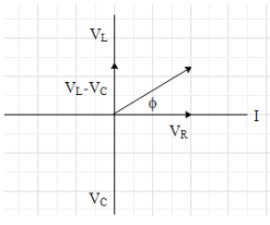
Let, the current through the circuit is in the positive x direction.
Now, we can say that the phase of the voltage through the inductor will be $\dfrac{\pi }{2}$ above in the anticlockwise direction. The phase of the voltage through the capacitor will be $\dfrac{\pi }{2}$ behind in the clockwise direction. The phase of the voltage through the resistance will be in the same direction as the current through the circuit.
The angle between the phases of the resultant of the ${{V}_{L}},{{V}_{c}},{{V}_{R}}$ and the phase of the current is called the phase angle of the circuit.
Mathematically, the phase angle can be expressed as,
$\begin{align}
& \tan \phi =\dfrac{{{V}_{L}}-{{V}_{C}}}{{{V}_{R}}}=\dfrac{I{{X}_{L}}-I{{X}_{C}}}{IR} \\
& \tan \phi =\dfrac{{{X}_{L}}-{{X}_{C}}}{R} \\
\end{align}$
Now, the ${{X}_{L}}$ and ${{X}_{C}}$can be expressed in terms of the frequency of the AC source as,
$\begin{align}
& {{X}_{L}}=\omega L=2\pi fL \\
& {{X}_{L}}=2\pi 50\dfrac{100}{\pi }\times {{10}^{-3}} \\
& {{X}_{L}}=10 \\
\end{align}$
And
$\begin{align}
& {{X}_{C}}=\dfrac{1}{\omega C}=\dfrac{1}{2\pi fC} \\
& {{X}_{C}}=\dfrac{1}{2\pi 50\dfrac{{{10}^{-3}}}{2\pi }} \\
& {{X}_{C}}=20 \\
\end{align}$
Now, putting the obtained values in the equation for the phase angle,
$\begin{align}
& \tan \phi =\dfrac{{{X}_{L}}-{{X}_{C}}}{R} \\
& \tan \phi =\dfrac{\left| 10-20 \right|}{10} \\
& \tan \phi =1 \\
& \phi ={{\tan }^{-1}}1 \\
& \phi ={{45}^{0}} \\
\end{align}$
So, the phase angle of the circuit is ${{45}^{0}}$.
The correct option is (C).
Note:
The notation ${{X}_{C}}$ is used in the above equations is the capacitive reactance and the notation ${{X}_{L}}$ is the inductive reactance. The reactance can be defined as the opposition offered by the capacitor and the inductor to the flow of the AC current through the circuit.
Complete answer:
The capacitor, inductor and the resistance are connected in series with an AC source.
Given, the capacitance is $\left( \dfrac{{{10}^{-3}}}{2\pi } \right)F$ and the inductance is $\left[ \dfrac{100}{\pi } \right]mH$ and the resistance is $10\Omega $
The voltage of the AC source is $220V$ and the frequency is $f=50Hz$
We need to find the phase angle of the circuit. Let us draw the phasor diagram for the circuit.
Let, the current through the circuit is in the positive x direction.
Now, we can say that the phase of the voltage through the inductor will be $\dfrac{\pi }{2}$ above in the anticlockwise direction. The phase of the voltage through the capacitor will be $\dfrac{\pi }{2}$ behind in the clockwise direction. The phase of the voltage through the resistance will be in the same direction as the current through the circuit.
The angle between the phases of the resultant of the ${{V}_{L}},{{V}_{c}},{{V}_{R}}$ and the phase of the current is called the phase angle of the circuit.
Mathematically, the phase angle can be expressed as,
$\begin{align}
& \tan \phi =\dfrac{{{V}_{L}}-{{V}_{C}}}{{{V}_{R}}}=\dfrac{I{{X}_{L}}-I{{X}_{C}}}{IR} \\
& \tan \phi =\dfrac{{{X}_{L}}-{{X}_{C}}}{R} \\
\end{align}$
Now, the ${{X}_{L}}$ and ${{X}_{C}}$can be expressed in terms of the frequency of the AC source as,
$\begin{align}
& {{X}_{L}}=\omega L=2\pi fL \\
& {{X}_{L}}=2\pi 50\dfrac{100}{\pi }\times {{10}^{-3}} \\
& {{X}_{L}}=10 \\
\end{align}$
And
$\begin{align}
& {{X}_{C}}=\dfrac{1}{\omega C}=\dfrac{1}{2\pi fC} \\
& {{X}_{C}}=\dfrac{1}{2\pi 50\dfrac{{{10}^{-3}}}{2\pi }} \\
& {{X}_{C}}=20 \\
\end{align}$
Now, putting the obtained values in the equation for the phase angle,
$\begin{align}
& \tan \phi =\dfrac{{{X}_{L}}-{{X}_{C}}}{R} \\
& \tan \phi =\dfrac{\left| 10-20 \right|}{10} \\
& \tan \phi =1 \\
& \phi ={{\tan }^{-1}}1 \\
& \phi ={{45}^{0}} \\
\end{align}$
So, the phase angle of the circuit is ${{45}^{0}}$.
The correct option is (C).
Note:
The notation ${{X}_{C}}$ is used in the above equations is the capacitive reactance and the notation ${{X}_{L}}$ is the inductive reactance. The reactance can be defined as the opposition offered by the capacitor and the inductor to the flow of the AC current through the circuit.
Recently Updated Pages
Master Class 12 Business Studies: Engaging Questions & Answers for Success
Master Class 12 Chemistry: Engaging Questions & Answers for Success
Master Class 12 Biology: Engaging Questions & Answers for Success
Class 12 Question and Answer - Your Ultimate Solutions Guide
Master Class 11 English: Engaging Questions & Answers for Success
Master Class 11 Maths: Engaging Questions & Answers for Success
Trending doubts
Which is more stable and why class 12 chemistry CBSE
Which are the Top 10 Largest Countries of the World?
Draw a labelled sketch of the human eye class 12 physics CBSE
Differentiate between homogeneous and heterogeneous class 12 chemistry CBSE
What are the major means of transport Explain each class 12 social science CBSE
Sulphuric acid is known as the king of acids State class 12 chemistry CBSE