


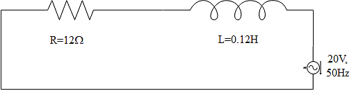
A $12\Omega $ resistor and an $0.21H$ inductor are connected in series to an AC source operating at $20V$, $50\dfrac{\text{cycles}}{\text{second}}$. The phase angle between the current and the source voltage will be given as,
$\begin{align}
& A.30{}^\circ \\
& B.40{}^\circ \\
& C.80{}^\circ \\
& D.90{}^\circ \\
\end{align}$
Answer
581.4k+ views
Hint: The tangent of the phase angle between the current and the voltage of the source found by taking the ratio of inductive reactance to the resistance in the circuit. In this the inductive reactance should be calculated by taking the product of angular frequency and the inductance value. Substitute this value of inductive reactance in the equation for phase angle and find out the answer. These all may help you to solve this question.
Complete step by step answer:
For finding the phase angle between the current and voltage source, the equation can be written as
$\phi ={{\tan }^{-1}}\left( \dfrac{{{X}_{L}}}{R} \right)$
Where ${{X}_{L}}$ be the inductive reactance and $R$ be the resistance of the resistor in the circuit.
Here we know that the inductive reactance is the product of the inductance value and the angular frequency. This can be expressed as an equation as,
${{X}_{L}}=\omega L$
Where $\omega $ be the angular frequency of the electric circuit and $L$ be the inductance of the inductor.
This angular frequency is calculated using the equation,
$\omega =2\pi f$
The value of frequency in the circuit is given as,
$f=50\text{cycles per second}$
Substituting this in the equation will give,
$\omega =2\pi \times 50=100\pi $
The angular frequency has been obtained this can substituted in the equation of inductive reactance,
Where it is already given that,
$L=0.21H$
That is
${{X}_{L}}=\omega L=100\pi \times 0.21=21\pi $
This value can now be substituted in the equation for the phase angle. It is already mentioned that,
$R=12\Omega $
That is,
$\begin{align}
& \phi ={{\tan }^{-1}}\dfrac{\omega L}{R}={{\tan }^{-1}}\dfrac{21\pi }{12} \\
& \phi ={{\tan }^{-1}}\left( \dfrac{11}{2} \right)=79.67{}^\circ \approx 80{}^\circ \\
\end{align}$
Therefore the correct answer is option C.
Note:
This kind of RL circuits are being used for DC power supplies to the RF amplifiers. This is done where in order to pass the DC bias current and block the RF coming back into the power supply are the use of inductors in it. Impedance of this kind of circuit is calculated by taking the square root of the sum of the squares of resistances and inductive reactance.
Recently Updated Pages
Master Class 12 English: Engaging Questions & Answers for Success
Master Class 12 Social Science: Engaging Questions & Answers for Success
Master Class 12 Maths: Engaging Questions & Answers for Success
Master Class 12 Economics: Engaging Questions & Answers for Success
Master Class 12 Physics: Engaging Questions & Answers for Success
Master Class 12 Business Studies: Engaging Questions & Answers for Success
Trending doubts
Which are the Top 10 Largest Countries of the World?
What are the major means of transport Explain each class 12 social science CBSE
Draw a labelled sketch of the human eye class 12 physics CBSE
Differentiate between insitu conservation and exsitu class 12 biology CBSE
RNA and DNA are chiral molecules their chirality is class 12 chemistry CBSE
RNA and DNA are chiral molecules their chirality is class 12 chemistry CBSE