


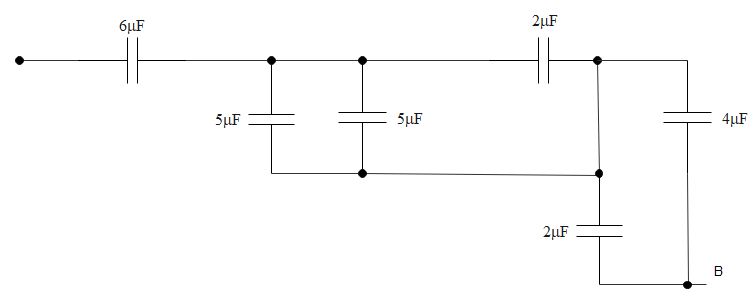
The equivalent capacitance between A and B in the circuit given below is:
A. $\text{4}\text{.9 }\!\!\mu\!\!\text{ F}$
B. $\text{3}\text{.6 }\!\!\mu\!\!\text{ F}$
C. $\text{5}\text{.4 }\!\!\mu\!\!\text{ F}$
D. $\text{2}\text{.4 }\!\!\mu\!\!\text{ F}$
Answer
603.3k+ views
Hint: For solving this question, we need to make sure that the simplified diagram of the circuit is correct. On the basis of the simplified circuit, we can figure out the parallel connections and the series connections. This will ultimately lead to the development of the equivalent capacitance of the circuit.
Complete step by step answer:
Before we move on with the solution of the question, we need to remember the following formulas, here are they:
Equivalent capacitance of the series circuit is denoted by ${{\text{C}}_{\text{series}}}$.
We should know that, ${{\text{C}}_{\text{series}}}\text{ = }\dfrac{\text{1}}{\dfrac{\text{1}}{{{\text{C}}_{\text{1}}}}\text{ + }\dfrac{\text{1}}{{{\text{C}}_{\text{2}}}}\text{ + }..............\text{ + }\dfrac{\text{1}}{{{\text{C}}_{\text{n}}}}}$${{\text{C}}_{\text{series}}}\text{ = }\dfrac{\text{1}}{\dfrac{\text{1}}{{{\text{C}}_{\text{1}}}}\text{ + }\dfrac{\text{1}}{{{\text{C}}_{\text{2}}}}\text{ + }..............\text{ + }\dfrac{\text{1}}{{{\text{C}}_{\text{n}}}}}$
Equivalent capacitance of the parallel circuit is denoted by ${{\text{C}}_{\text{parallel}}}$.
We should know that, ${{\text{C}}_{\text{parallel}}}\text{ = }{{\text{C}}_{\text{1}}}\text{ + }{{\text{C}}_{\text{2}}}\text{ + }..........\text{ + }{{\text{C}}_{\text{n}}}$
Now let us draw the simplified structure of the circuit that is given. We can draw it like the one shown below for ease in calculation.
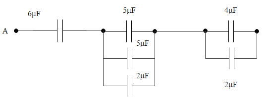
Therefore, we can determine the equivalent capacitance to be
${{\text{E}}_{\text{q}}}\text{ = 5 + 5 + 2 = 12 }\!\!\mu\!\!\text{ F}$
This is the equivalent capacitance of the capacitor bank in the middle of the circuit as given in the above diagram.
${{\text{E}}_{\text{q}}}\text{ = 4 + 2 = 8 }\!\!\mu\!\!\text{ F}$
This is the equivalent capacitance of the capacitor bank in the right end of the circuit as drawn above.
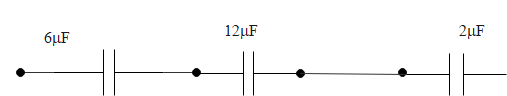
$\therefore$ Parallel connection of all the series equivalent capacitors rounds up to a total of
${{\text{E}}_{\text{q}}}\text{ = 2}\text{.4 }\!\!\mu\!\!\text{ F}$
Note: We should know the definition of the quantity that is mentioned in the question. By capacitance we mean the electric charge in a system, which is expressed in accordance to the electric potential value. The symbol of expression of capacitance is C. The unit of capacitance is Farad. Farad is the ratio between charge and voltage. The unit of charge is coulomb and that of the voltage is volts. So, Farad is coulomb divided by volts.
Complete step by step answer:
Before we move on with the solution of the question, we need to remember the following formulas, here are they:
Equivalent capacitance of the series circuit is denoted by ${{\text{C}}_{\text{series}}}$.
We should know that, ${{\text{C}}_{\text{series}}}\text{ = }\dfrac{\text{1}}{\dfrac{\text{1}}{{{\text{C}}_{\text{1}}}}\text{ + }\dfrac{\text{1}}{{{\text{C}}_{\text{2}}}}\text{ + }..............\text{ + }\dfrac{\text{1}}{{{\text{C}}_{\text{n}}}}}$${{\text{C}}_{\text{series}}}\text{ = }\dfrac{\text{1}}{\dfrac{\text{1}}{{{\text{C}}_{\text{1}}}}\text{ + }\dfrac{\text{1}}{{{\text{C}}_{\text{2}}}}\text{ + }..............\text{ + }\dfrac{\text{1}}{{{\text{C}}_{\text{n}}}}}$
Equivalent capacitance of the parallel circuit is denoted by ${{\text{C}}_{\text{parallel}}}$.
We should know that, ${{\text{C}}_{\text{parallel}}}\text{ = }{{\text{C}}_{\text{1}}}\text{ + }{{\text{C}}_{\text{2}}}\text{ + }..........\text{ + }{{\text{C}}_{\text{n}}}$
Now let us draw the simplified structure of the circuit that is given. We can draw it like the one shown below for ease in calculation.
Therefore, we can determine the equivalent capacitance to be
${{\text{E}}_{\text{q}}}\text{ = 5 + 5 + 2 = 12 }\!\!\mu\!\!\text{ F}$
This is the equivalent capacitance of the capacitor bank in the middle of the circuit as given in the above diagram.
${{\text{E}}_{\text{q}}}\text{ = 4 + 2 = 8 }\!\!\mu\!\!\text{ F}$
This is the equivalent capacitance of the capacitor bank in the right end of the circuit as drawn above.
$\therefore$ Parallel connection of all the series equivalent capacitors rounds up to a total of
${{\text{E}}_{\text{q}}}\text{ = 2}\text{.4 }\!\!\mu\!\!\text{ F}$
Note: We should know the definition of the quantity that is mentioned in the question. By capacitance we mean the electric charge in a system, which is expressed in accordance to the electric potential value. The symbol of expression of capacitance is C. The unit of capacitance is Farad. Farad is the ratio between charge and voltage. The unit of charge is coulomb and that of the voltage is volts. So, Farad is coulomb divided by volts.
Recently Updated Pages
Master Class 10 Computer Science: Engaging Questions & Answers for Success
Master Class 10 General Knowledge: Engaging Questions & Answers for Success
Master Class 10 English: Engaging Questions & Answers for Success
Master Class 10 Social Science: Engaging Questions & Answers for Success
Master Class 10 Maths: Engaging Questions & Answers for Success
Master Class 10 Science: Engaging Questions & Answers for Success
Trending doubts
What is the median of the first 10 natural numbers class 10 maths CBSE
Which women's tennis player has 24 Grand Slam singles titles?
Who is the Brand Ambassador of Incredible India?
Why is there a time difference of about 5 hours between class 10 social science CBSE
Write a letter to the principal requesting him to grant class 10 english CBSE
State and prove converse of BPT Basic Proportionality class 10 maths CBSE