


In the adjacent diagram A and B represents two inputs and C represent the output, the circuit represents
(A). NOR gate
(B). AND gate
(C). NAND gate
(D). OR gate

Answer
571.2k+ views
Hint: The given circuit connects diodes to form a gate. When we apply potential difference across the diodes, we get a certain output at C. The inputs given and the output received as a result from the given circuit can be used to make a truth table. The truth table will tell us the type of gate formed by the circuit.
Complete answer:
A diode is a semiconductor device which allows the current to flow in one direction.
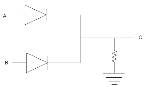
In the figure given above, A and B are diodes. If a potential difference is applied across AB such that A is positive. Then, potential at A is equal to potential at C. Therefore,
A=C
Similarly, if B is positive, the potential at B will now be equal to potential at C. Therefore,
B=C
If there is no potential at both A and B, then there will be no potential at C. Therefore,
C=0
Its truth table can be drawn as
The above given table is a table of an OR gate. Thus, the given setting represents an OR gate.
Therefore, the above circuit represents an OR gate. Hence, the correct option is (D).
Note:
Gates are a combination of diodes and are basic blocks of any digital system which take binary inputs to give one binary output. A binary number is expressed in base 2 and uses only 0 and 1. More complex gates can be made by combining simple gates. Earth is a conductor of electricity that is still complete when the load is grounded.
Complete answer:
A diode is a semiconductor device which allows the current to flow in one direction.
In the figure given above, A and B are diodes. If a potential difference is applied across AB such that A is positive. Then, potential at A is equal to potential at C. Therefore,
A=C
Similarly, if B is positive, the potential at B will now be equal to potential at C. Therefore,
B=C
If there is no potential at both A and B, then there will be no potential at C. Therefore,
C=0
Its truth table can be drawn as
| A | B | C |
| 1 | 0 | 1 |
| 0 | 1 | 1 |
| 0 | 0 | 0 |
The above given table is a table of an OR gate. Thus, the given setting represents an OR gate.
Therefore, the above circuit represents an OR gate. Hence, the correct option is (D).
Note:
Gates are a combination of diodes and are basic blocks of any digital system which take binary inputs to give one binary output. A binary number is expressed in base 2 and uses only 0 and 1. More complex gates can be made by combining simple gates. Earth is a conductor of electricity that is still complete when the load is grounded.
Recently Updated Pages
Master Class 12 Business Studies: Engaging Questions & Answers for Success
Master Class 12 Biology: Engaging Questions & Answers for Success
Master Class 12 Chemistry: Engaging Questions & Answers for Success
Class 12 Question and Answer - Your Ultimate Solutions Guide
Master Class 11 Social Science: Engaging Questions & Answers for Success
Master Class 11 English: Engaging Questions & Answers for Success
Trending doubts
Which are the Top 10 Largest Countries of the World?
Draw a labelled sketch of the human eye class 12 physics CBSE
Name the crygenes that control cotton bollworm and class 12 biology CBSE
Differentiate between homogeneous and heterogeneous class 12 chemistry CBSE
Ribosomal RNA is actively synthesised in A Nucleoplasm class 12 biology CBSE
How many molecules of ATP and NADPH are required information class 12 biology CBSE