


In an n-p-n transistor circuit, the collector current is 9 mA. If \[90\% \] of the electrons emitted reach the collector. Then the emitter current is
\[A)\;\;\;\;8.1{\text{ }}mA\]
\[B)\;\;\;\;8{\text{ }}mA\]
\[C)\;\;\;\;9{\text{ }}mA\]
\[D)\;\;\;\;10{\text{ }}mA\]
Answer
587.4k+ views
Hint:Remember the direction of the flow of current and electrons in an n-p-n transistor. The direction of the flow of electrons is from the emitter region to the collector region.
Complete step by step answer:
According to the question, it is given that it is an n-p-n circuit. NPN transistor is the transistor in which one p-type material is placed between two n-type materials.
The NPN transistor amplifies the weak signals which enter into the base and starts producing the strong amplified signals at the collector end.
In NPN transistors, the direction of flow of an electron is from the emitter to the collector region owing to which the current produces in the transistor.
These types of transistors are mostly used in the circuit because their majority charge carriers are electrons which have high mobility as compared to positively charged holes.
Also, the collector current is \[{I_C} = {\text{ }}9{\text{ }}mA\]
And it is also given that \[90\% \] of electrons from the emitter reaches the collector.
So we have \[{I_C} = {\text{ }}\dfrac{9}{{10}}{\text{ }}{I_E}\]
\[ \Rightarrow {I_E}\; = {\text{ }}\dfrac{{10}}{9}{\text{ }}{I_C}\]
Substitute the value of \[{I_C} = {\text{ }}9{\text{ }}mA\] and we get
\[ = \dfrac{{10}}{9}{\text{ }} \times {\text{ }}9{\text{ }}\]
Cancel the terms we get,
\[ = {\text{ }}10{\text{ }}mA\]
Therefore option D is correct.
Additional information:
The NPN transistor contains the two diodes connected back to back. The diode present on the left side is called an emitter-base diode, and the diodes on the right side are called the collector-base diode.
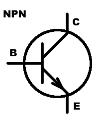
Note: In the diagram, the arrow is representing the flow of current which is from collector to emitter but the direction of the flow of electrons is reverse of that of the flow of current i.e., emitter to collector.
Complete step by step answer:
According to the question, it is given that it is an n-p-n circuit. NPN transistor is the transistor in which one p-type material is placed between two n-type materials.
The NPN transistor amplifies the weak signals which enter into the base and starts producing the strong amplified signals at the collector end.
In NPN transistors, the direction of flow of an electron is from the emitter to the collector region owing to which the current produces in the transistor.
These types of transistors are mostly used in the circuit because their majority charge carriers are electrons which have high mobility as compared to positively charged holes.
Also, the collector current is \[{I_C} = {\text{ }}9{\text{ }}mA\]
And it is also given that \[90\% \] of electrons from the emitter reaches the collector.
So we have \[{I_C} = {\text{ }}\dfrac{9}{{10}}{\text{ }}{I_E}\]
\[ \Rightarrow {I_E}\; = {\text{ }}\dfrac{{10}}{9}{\text{ }}{I_C}\]
Substitute the value of \[{I_C} = {\text{ }}9{\text{ }}mA\] and we get
\[ = \dfrac{{10}}{9}{\text{ }} \times {\text{ }}9{\text{ }}\]
Cancel the terms we get,
\[ = {\text{ }}10{\text{ }}mA\]
Therefore option D is correct.
Additional information:
The NPN transistor contains the two diodes connected back to back. The diode present on the left side is called an emitter-base diode, and the diodes on the right side are called the collector-base diode.
Note: In the diagram, the arrow is representing the flow of current which is from collector to emitter but the direction of the flow of electrons is reverse of that of the flow of current i.e., emitter to collector.
Recently Updated Pages
Basicity of sulphurous acid and sulphuric acid are
Master Class 11 Business Studies: Engaging Questions & Answers for Success
Master Class 11 Computer Science: Engaging Questions & Answers for Success
Master Class 11 Economics: Engaging Questions & Answers for Success
Master Class 11 Social Science: Engaging Questions & Answers for Success
Master Class 11 English: Engaging Questions & Answers for Success
Trending doubts
Draw a diagram of nephron and explain its structur class 11 biology CBSE
Explain zero factorial class 11 maths CBSE
Chemical formula of Bleaching powder is A Ca2OCl2 B class 11 chemistry CBSE
Name the part of the brain responsible for the precision class 11 biology CBSE
The growth of tendril in pea plants is due to AEffect class 11 biology CBSE
One Metric ton is equal to kg A 10000 B 1000 C 100 class 11 physics CBSE