


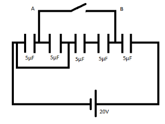
Find the charge that flows from point $A$ to $B$, when the switch is closed.
Answer
522.9k+ views
Hint: A capacitor is a device that stores electrical energy in an electric field. It is a passive electronic component with two terminals. The effect of a capacitor is known as capacitance. The resistance of an ideal capacitor is zero. The reactance of an ideal capacitor, and therefore its impedance, is negative for all frequency and capacitance value. To solve this problem we should try to turn a complex capacitor system into a simple one. We should know how to calculate effective capacitances of a system.
Complete step by step answer:
Rearranging the circuit
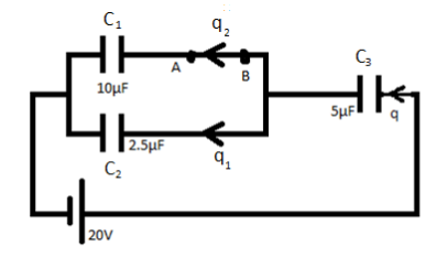
$q = CV$
Equivalent capacitance of the circuit is
${C_1}\,and\,{C_2}$ are in parallel
So
${C_T} = {C_1} + {C_2}$
Put the value
${C_T} = 10 + 2.5$
$\Rightarrow {C_T} = 12.5\mu F$
${C_T}\,and\,{C_3}$ are in series
${C_{eq}} = \dfrac{{{C_3} \times {C_T}}}{{{C_3} + {C_T}}}$
Put the value
${C_{eq}} = \dfrac{{5 \times 12.5}}{{12.5 + 5}}$
\[\Rightarrow {C_{eq}} = \dfrac{{25}}{7}\mu F\]
As we know that
$q = CV$
Put the value
$q = \dfrac{{25}}{7} \times 20$
$\Rightarrow q = \dfrac{{500}}{7}\mu F$
Now apply Kirchhoff’s Voltage Law
It states that “the algebraic sum of all voltage difference is equal to zero.”
$\sum\limits_{}^{} V = 0$
$ \Rightarrow 20 = \dfrac{{20 \times 25}}{{7 \times 5}} + \dfrac{{{q_1}}}{{2.5}}$
$ \Rightarrow {q_1} = \dfrac{{100}}{7}\mu F$
Charge flow from $B$ to $A$
$ \Rightarrow {q_2} = \dfrac{{400}}{7}\mu F$
Charge flow from A to B
$ \therefore {q_2} = - \dfrac{{400}}{7}\mu F$
Hence, the charge that flows from point $A$ to $B$ is $- \dfrac{{400}}{7}\,\mu F$.
Note: In a simple plate capacitor, a voltage applied between two conductive plates creates a uniform electric field between those plates. The electric field strength in a capacitor is directly proportional to the voltage applied and inversely proportional to the distance between the plates. The energy stored in a capacitor can be expressed in three ways, energy in joules, charge is in coulombs, and capacitance in farads.
Complete step by step answer:
Rearranging the circuit
$q = CV$
Equivalent capacitance of the circuit is
${C_1}\,and\,{C_2}$ are in parallel
So
${C_T} = {C_1} + {C_2}$
Put the value
${C_T} = 10 + 2.5$
$\Rightarrow {C_T} = 12.5\mu F$
${C_T}\,and\,{C_3}$ are in series
${C_{eq}} = \dfrac{{{C_3} \times {C_T}}}{{{C_3} + {C_T}}}$
Put the value
${C_{eq}} = \dfrac{{5 \times 12.5}}{{12.5 + 5}}$
\[\Rightarrow {C_{eq}} = \dfrac{{25}}{7}\mu F\]
As we know that
$q = CV$
Put the value
$q = \dfrac{{25}}{7} \times 20$
$\Rightarrow q = \dfrac{{500}}{7}\mu F$
Now apply Kirchhoff’s Voltage Law
It states that “the algebraic sum of all voltage difference is equal to zero.”
$\sum\limits_{}^{} V = 0$
$ \Rightarrow 20 = \dfrac{{20 \times 25}}{{7 \times 5}} + \dfrac{{{q_1}}}{{2.5}}$
$ \Rightarrow {q_1} = \dfrac{{100}}{7}\mu F$
Charge flow from $B$ to $A$
$ \Rightarrow {q_2} = \dfrac{{400}}{7}\mu F$
Charge flow from A to B
$ \therefore {q_2} = - \dfrac{{400}}{7}\mu F$
Hence, the charge that flows from point $A$ to $B$ is $- \dfrac{{400}}{7}\,\mu F$.
Note: In a simple plate capacitor, a voltage applied between two conductive plates creates a uniform electric field between those plates. The electric field strength in a capacitor is directly proportional to the voltage applied and inversely proportional to the distance between the plates. The energy stored in a capacitor can be expressed in three ways, energy in joules, charge is in coulombs, and capacitance in farads.
Recently Updated Pages
Basicity of sulphurous acid and sulphuric acid are
Master Class 12 English: Engaging Questions & Answers for Success
Master Class 12 Social Science: Engaging Questions & Answers for Success
Master Class 12 Maths: Engaging Questions & Answers for Success
Master Class 12 Economics: Engaging Questions & Answers for Success
Master Class 12 Physics: Engaging Questions & Answers for Success
Trending doubts
Draw a labelled sketch of the human eye class 12 physics CBSE
Which are the Top 10 Largest Countries of the World?
Draw ray diagrams each showing i myopic eye and ii class 12 physics CBSE
Giving reasons state the signs positive or negative class 12 physics CBSE
Explain esterification reaction with the help of a class 12 chemistry CBSE
What is defined as a solenoid Depict a diagram with class 12 physics CBSE