


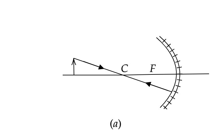
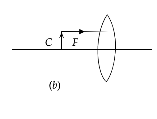
Complete the following ray diagrams. State the size and nature of the image formed in each case.
Answer
598.5k+ views
Hint: To complete any ray diagram and to find the image position and size, we need to know the rules for drawing ray diagrams, such as, a light ray travelling parallel to the principal axis passes through the focus of the mirror or the lens; a light ray passing through the centre of curvature of a mirror or the pole of a lens passes through un-deviated without suffering any reflection or refraction.
Complete step by step solution:
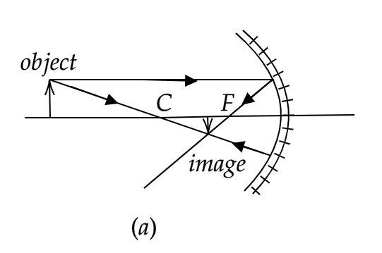
In the case of figure (a), we have a convex mirror and an object is kept beyond the centre of curvature of the mirror (denoted by C). We have been provided with a single ray of light passing through the centre of curvature (C) of the mirror and hence it retraces its path after reflection from the mirror. The minimum requirement for the image of a point that does not lie on the principal axis is two light rays. So we will consider another light ray incident on the mirror parallel to the principal axis. As discussed above, a light ray parallel to the principal axis passes through the focus of the mirror (denoted by F). The image formed will thus be real and inverted and will be formed between the focus and the centre of curvature of the mirror. The size of the image will be less than that of the object, almost diminished. To visualise this procedure, here is the final ray diagram.
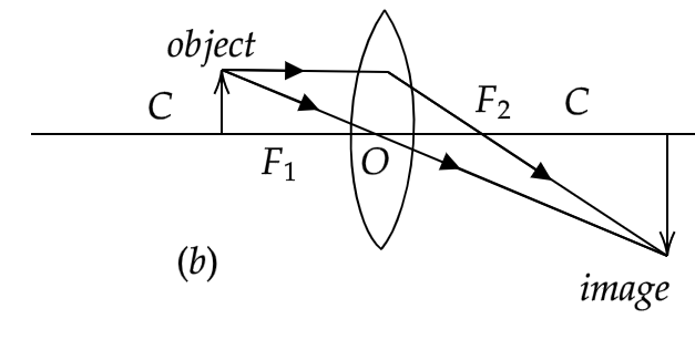
Moving on to figure (b), we have been given a bi-convex lens and the object is placed between the centre of curvature and the focus of the lens. A light ray parallel to the principal axis has been provided to us. We know that this light ray will pass through the focus on the other side of the lens after refraction. We need to consider another light ray. We’ll take a light ray originating from the object and passing through the pole of the lens. This light ray will pass through un-deviated and will intersect the previous light ray beyond the centre of curvature on the other side of the lens. The image formed will be real and inverted. The image size will be larger than the object size, almost magnified. The final ray diagram will look something like:
Note: If you would have noticed, we have only traced light rays starting from the top of the object. We did this because the principal axis of a spherical mirror or a lens behaves like a normal and as such, for any object lying on the principal axis, the spherical mirror or the lens behaves like a plane mirror and the image is formed behind the mirror or lens at a distance equal to the object distance from the mirror or the lens.
Complete step by step solution:
In the case of figure (a), we have a convex mirror and an object is kept beyond the centre of curvature of the mirror (denoted by C). We have been provided with a single ray of light passing through the centre of curvature (C) of the mirror and hence it retraces its path after reflection from the mirror. The minimum requirement for the image of a point that does not lie on the principal axis is two light rays. So we will consider another light ray incident on the mirror parallel to the principal axis. As discussed above, a light ray parallel to the principal axis passes through the focus of the mirror (denoted by F). The image formed will thus be real and inverted and will be formed between the focus and the centre of curvature of the mirror. The size of the image will be less than that of the object, almost diminished. To visualise this procedure, here is the final ray diagram.
Moving on to figure (b), we have been given a bi-convex lens and the object is placed between the centre of curvature and the focus of the lens. A light ray parallel to the principal axis has been provided to us. We know that this light ray will pass through the focus on the other side of the lens after refraction. We need to consider another light ray. We’ll take a light ray originating from the object and passing through the pole of the lens. This light ray will pass through un-deviated and will intersect the previous light ray beyond the centre of curvature on the other side of the lens. The image formed will be real and inverted. The image size will be larger than the object size, almost magnified. The final ray diagram will look something like:
Note: If you would have noticed, we have only traced light rays starting from the top of the object. We did this because the principal axis of a spherical mirror or a lens behaves like a normal and as such, for any object lying on the principal axis, the spherical mirror or the lens behaves like a plane mirror and the image is formed behind the mirror or lens at a distance equal to the object distance from the mirror or the lens.
Recently Updated Pages
Master Class 12 Social Science: Engaging Questions & Answers for Success
Master Class 12 Physics: Engaging Questions & Answers for Success
Master Class 12 Maths: Engaging Questions & Answers for Success
Master Class 12 Economics: Engaging Questions & Answers for Success
Master Class 12 Chemistry: Engaging Questions & Answers for Success
Master Class 12 Business Studies: Engaging Questions & Answers for Success
Trending doubts
Which are the Top 10 Largest Countries of the World?
Draw a labelled sketch of the human eye class 12 physics CBSE
Explain the structure of megasporangium class 12 biology CBSE
What are the major means of transport Explain each class 12 social science CBSE
How many chromosomes are found in human ovum a 46 b class 12 biology CBSE
The diagram of the section of a maize grain is given class 12 biology CBSE